Everyone is an inventor and especially you!!

Earth/Ground
In electronics you often come across the words earth or Ground (GND).
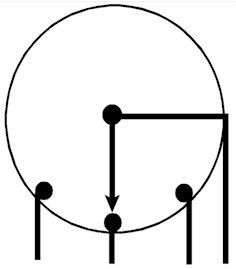
You probably already know that this has little to do with garden soil or potting soil. What is meant by earth? Suppose you have a small steel ball. You stuff electrons into the sphere. What happens then? The electrons are distributed as evenly as possible over the sphere and the sphere acquires a negative charge. An electron is extremely small, so you cannot even measure the first few thousand electrons that you stuff into the sphere. The planet earth on which we live is also more or less a sphere. That sphere contains many substances such as water with salts dissolved in it, minerals including metals, and so on. Many materials that conduct reasonably well. The planet Earth is a huge sphere. If you pump a few billion electrons into it, the result is not even measurable. Sometimes you can see billions of electrons being pumped into the Earth when lightning strikes. Yet the earth receives next to nothing charge.
You can think of the earth as a huge vessel into which we can pour all the excess water, or, if we need it, take it out. In electronics we use the earth as a storage place for electrons. The earth as a huge capacitor. If we want to protect circuits or electrical equipment against voltage peaks, we ensure that those peaks can easily flow to earth. For example, the washing machine in your house is also grounded. If a wire breaks in the washing machine and 230 V appears on the outside, it flows immediately to earth so that the washing machine remains safe. How?
Yes, it really is true that we stick a well-conducting pin deep into the ground for this. Most houses have their own earth pin.
Analogue
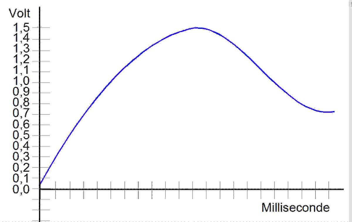
Everything in nature is analog. A sound can become louder or softer without hearing steps. The value changes smoothly. And that is also the case with light intensity and color. If we translate natural phenomena such as light, sound, color and movement into electrical signals using a sensor, these are analog signals. In the picture you see an analog signal that, in this case, takes on any value between 0 V and 1.5 V. Most electronic components can handle analog signals well. But there are important parts that only know digital signals. See digital.
Atomic model
An atom is the smallest building block that still has the properties of the material made with that building block. Iron, for example, consists of iron atoms. Atoms also often occur in combinations, we call molecules. The vast majority of materials consist of molecules. Because we cannot see an atom, we try to imagine as best as possible what it might look like and how it is put together. That is why we create a model, a simplified representation of reality. Just like you can make a drawing of a house, for example. The drawing is never exactly the same as the house, but you can still imagine the house. In our model the atom consists for the most part of NOTHING! In the center there is a core with small positive and neutral particles. Surrounding it, at a very large fixed distance, is a kind of spherical cloud with one or more very small negative particles: electrons. All particles within the atom are drawn in the model as small spheres. To get an idea of the enormous void: if a euro on the Tower in London represents the nucleus of an atom, the nearest electron is the tip of a needle on the City Federal building in Birmingham.
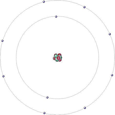
And yet an atom itself is unimaginably small. There are more atoms in a glass of water than stars in the Milky Way! The electrons in the cloud revolve around the nucleus and their charge is exactly balanced with the charge of the nucleus. If the nucleus becomes larger, more electrons must move around it to maintain equilibrium. However, the first cloud is “full” with two electrons. If the atom needs more electrons, it uses a second cloud at a greater fixed distance that can accommodate a maximum of 8 electrons. When that “cloud” is full, the next electrons have to keep a greater distance and so on. Because the clouds are at a fixed distance, they are called shells. The properties of an atom are determined by the charge of the nucleus and the number of electrons floating around it, especially the electrons in the outer shell. The composition of atoms is mapped out in the periodic table of elements, which you may be familiar with from physics and chemistry. What you can easily imagine is that the bond between an electron and the nucleus becomes smaller and smaller as the distance increases. Very large atoms are therefore often unstable and can only exist for a short time before they fall apart. 103 electrons seems to be the maximum.
ions
Strong attractive forces can cause an atom to lose or gain electrons from another atom. When an atom loses or gains an electron, we call the result an ion. Because ions have a charge, they play an important role in electronics, but also in chemistry.
Battery
A battery is an electron pump. Thanks to a chemical process in the battery, a voltage difference is created on the poles (connections) that we can use as an energy source. When the supply of chemicals in the battery is exhausted, we call the battery empty. A normal battery then ends up in the waste dump or is (partially) reused. With rechargeable batteries you can reverse the discharge process by putting electrons back into them. That's called charging. Unfortunately, this does not last indefinitely and the battery is exhausted after 10 to 100 charges.
Batteries are very convenient to use. Almost everything is now becoming wireless, such as your mobile phone, the drill, your headphones. And with a car, a cord is of course really impossible. But there is also a downside; Rare raw materials are used for batteries, which are often extracted from the ground at the expense of local populations. And the enormous use of batteries and the dumping of the waste caused by them places an enormous burden on the environment. So use a mains power supply if possible and if batteries are really necessary, choose rechargeable batteries.
Capacitor
A capacitor is a component that blocks direct current and passes alternating current. A capacitor can also be used to store (a small amount of) energy.
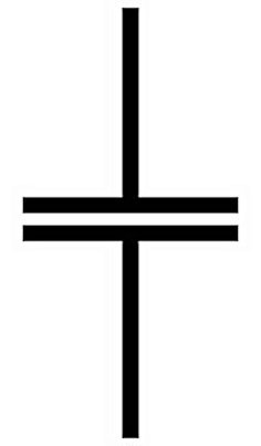
symbol
capacitor

A capacitor consists of two conducting plates with a very thin insulation layer between them. If you now send electrons to one of the plates (we'll call it plate A), it will get a negative charge. Because the plates are so close together, the electrons in the other plate (plate B) are pushed away. It seems as if the current passes through the capacitor for a moment, but when the plate is completely full of electrons, the movement stops. If you then remove all the electrons from plate A, it becomes positively charged and the electrons are attracted to plate B. Again it seems as if the electrons are moving through the capacitor, but that is not the case.
It is only the charging and discharging of plate A that causes the (opposite) discharging and charging of plate B. Plate B therefore always takes on the opposite charge of plate A. And this also applies the other way around, a capacitor has no polarity (plus and minus pole). The larger the plates, the more cargo can fit on them. The size of the plates and therefore the amount of charge that can fit on them is called the capacity. The unit of capacitance is called Farad. Most capacitors we use are much smaller than 1 Farad. You will encounter values from a few picofarads (pF) to several thousand microfarads (µf). (See multipliers)
You can imagine that capacitors with a small capacity quickly fill up. So they can only pass on very fast changes. The greater the capacity, the greater the wavelength that can be transmitted.
The insulator between the plates is very thin. If the voltage becomes too high, the insulator will break and a short circuit will occur between the plates. The maximum voltage is therefore always stated for a capacitor.
Bucket capacitor
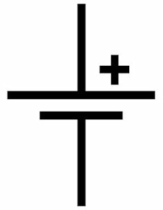
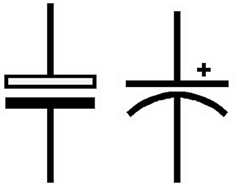
There are special bucket capacitors that are used to store many more electrons. Officially they are called 'electrolytic capacitors.' These capacitors are polar and therefore have a positive pole and a negative pole. Connecting it the other way around destroys the electrolytic capacitor, sometimes with a big bang and a lot of stench. Be careful, those fumes are quite toxic! You can use an electrolytic capacitor as a storage container for electrons. If you have too much, or more than enough, fill the bucket. As soon as you fall short, empty the bucket. To show that a bucket capacitor is an electrolytic capacitor, it has a different symbol and there is a plus and a minus sign on the capacitor. The open bar of the symbol is the positive terminal of the capacitor. The English symbol, which is next to it, is also widely used.
Water model of the capacitor
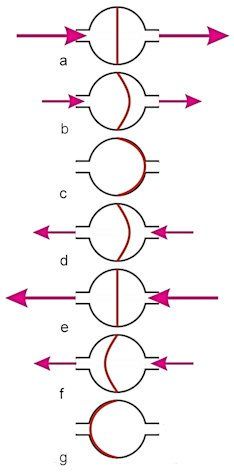
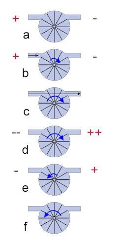
How a capacitor works is easy to explain with the help of a water model: Here, a capacitor is a vessel with a sheet of rubber in the middle. At rest, the skin hangs in the center of the barrel.
a) If we apply pressure, the sheet will immediately stretch. A lot of current flows, but the voltage across the capacitor is virtually 0!
b) The further the sheet is stretched, the more resistance it will provide.
c) Eventually it reaches the final position and increasing the pressure no longer produces any movement. There is now full voltage, but no current flows!
d) If we now remove the water pressure, the rubber sheet will spring back and exert pressure itself for a while! So current flows for a very short time when we remove the voltage.e) If we reverse the water pressure, the pressure of the sheet will be on top of the water pressure.
f) The movement now repeats in the other direction.
In this way, an alternating current movement can be transmitted through a capacitor.
The voltage and current behavior of a capacitor in detail.
Now let's see, with the help of Ohm's law, what exactly the capacitor does.
When I apply voltage to a capacitor, it first behaves like a short circuit. The resistance at that moment is almost 0 Ω! So a very large current is already flowing, while the voltage is still almost 0 V. Something like this: U = I x R, R = 0.01 Ω. If I = 10 A then the voltage will only be 0.1 V! If the rubber sheet is stretched further and further, it will stop the current more and more, in other words: the resistance of the capacitor becomes increasingly greater and even almost infinitely greater when the rubber is completely against the output. The resistance is then very high and the current is very small. Something like this: U = I x R, I = 0.00001 A and the resistance = 100000 Ω, then U is 10 Volts. That is special, first the current reaches maximum at zero volts and then the voltage becomes high, while almost no current flows. The voltage lags behind the current. With DC voltage it ends here, the voltage remains high and the resistance is virtually infinite, so the current is practically 0.
This is very different with an alternating voltage! After all, the voltage keeps changing, causing the capacitor to keep repeating the pattern. You will then see that current always flows first and then voltage appears. We call this lag: With an alternating voltage, the voltage across a capacitor lags the current by 90°!
AC resistance of a capacitor
A capacitor does not pass direct current, but it does pass alternating current. The extent to which the capacitor hinders the transmitted alternating current is called impedance with the symbol XC. Impedance therefore corresponds to alternating current resistance and therefore has ohms as a unit. The AC resistance of a capacitor is given as follows
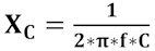
Where f is the frequency of the alternating current in Hertz and C is the capacitance of the capacitor in Farads. And, if you don't already know; π is the Greek letter pi and it stands for the number 3.14. To find the AC resistance, first multiply the capacitance by the frequency. Then you multiply that number by 6.28 (2x3.14). Finally, you divide 1 by the result of that sum. The alternating current resistance therefore depends on the frequency! The higher the frequency, the lower the alternating current resistance of a capacitor. A capacitor indeed transmits high frequencies more easily than low frequencies and you will see in circuits that we can make good use of this.
Energy storage/DC behavior of a capacitor
If you charge a capacitor and then put it away, the voltage remains in it, just like an inflated balloon. We used to play pranks on this by charging a capacitor (that was suitable for this) with a high voltage and then putting it back in the cupboard. The next person who took the capacitor and connected it was, to his or her horror, seeing quite a few sparks!
The energy that you can store in a capacitor is equal to:
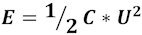
Where E is the stored energy, C is the capacitance of the capacitor and U is the voltage. To charge a capacitor you always need a limiting resistor, as an uncharged capacitor has a very low resistance, if not a short circuit. The enormous 'starting current' could destroy the power supply and the capacitor. Therefore, a small series resistance R is included in the circuit.
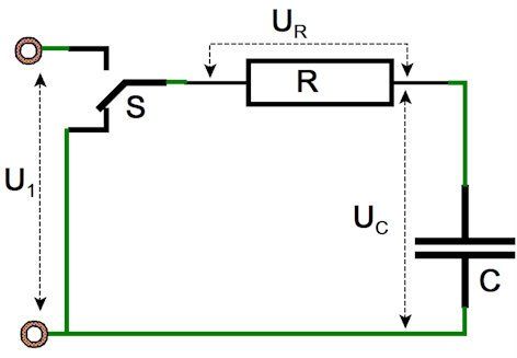
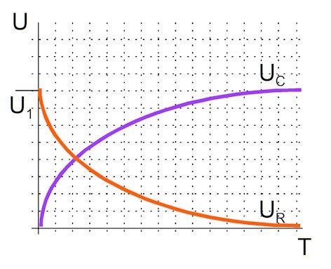
As soon as we switch switch S to U1, the capacitor starts charging. At t = 0 the capacitor is a short circuit and all voltage falls across the resistor R. The maximum current flows through the resistor R (I = U1/R). The capacitor starts to charge and thus the resistance of the capacitor increases. Charging takes place according to an exponential function: the resistance of C continues to increase, making charging slower and slower. After the charging time: R*C (Ω and farad) the capacitor is 63% charged. After 5*R*C the capacitor is fully charged and no more current flows. The voltage U1 is now completely across the capacitor C. If we now reset the switch to 0 V, exactly the opposite will happen. The capacitor will discharge through the resistor R according to an exponential function. The fully charged capacitor carries the voltage U1 and causes a large current in the resistor. The more the voltage drops, the smaller the current through the resistor and after the discharge time 5*R*C the capacitor is completely discharged.
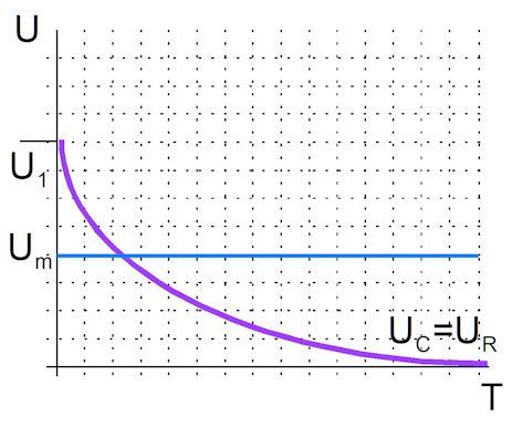
When using a capacitor as an energy supply, you must take into account the lowest voltage Um at which your connected circuit still works. The graph below shows that only a small part of the capacity can be used. After that, the voltage already drops below the minimum operating voltage. The solution is a switching power supply that increases the voltage. You will of course find examples of this in the example circuits: circuit 12 and circuit 13.
Applications: Capacitors are widely used in filters because the alternating current resistance depends on the frequency. You also use capacitors if you only want to transmit alternating current signals, the so-called coupling capacitors.
Digital.
Your telephone, television, computer and much more equipment is equipped with processors, often microcontrollers (see microcontrollers). A processor can only process digital signals. This means that most electronics work digitally. Digital only has two values: on and off or one and zero. Analog signals such as brightness or volume must therefore first be made digital before they can be stored in your phone or sent via WiFi.
To digitalize, for example, a rising and falling volume, we divide the time into fixed steps. With each step of, for example, 1 microsecond, the volume is measured and saved as a digital number. The volume in your PC consists of a table with a number for every microsecond! The entire set of digital numbers can be stored in memory! This can also be done with colors and amount of light and so on. There are several ways to translate analog values into digital values, but it will never be exactly the analog value! The big advantage is that with digital signals you are hardly bothered by noise. (See noise)
Digital number
What do digital numbers look like?
To help you imagine this, let's first look at how people actually learned to count, namely on their fingers!
We have ten fingers and can therefore naturally count to ten. Then we have a problem, because we run out of fingers. We solved that very conveniently by saying: we remember that we have used all the fingers once and simply start counting again. That's how we invented the ten. In the past, if you wanted to recite the number 23 to your boyfriend or girlfriend at school, you would first secretly hold up 2 x 10 fingers and then another 3. This is officially called two tens and three ones. However, if we have filled 10 tens, we have the same problem again and therefore continue with hundreds. So we can always count a maximum of 10 from each group. We call that the decimal system. The computer uses the same trick, except 'it' only has 'one finger' good for zero and one. That is why he always calculates in multiples of two instead of ten, i.e. in the dual or binary system.
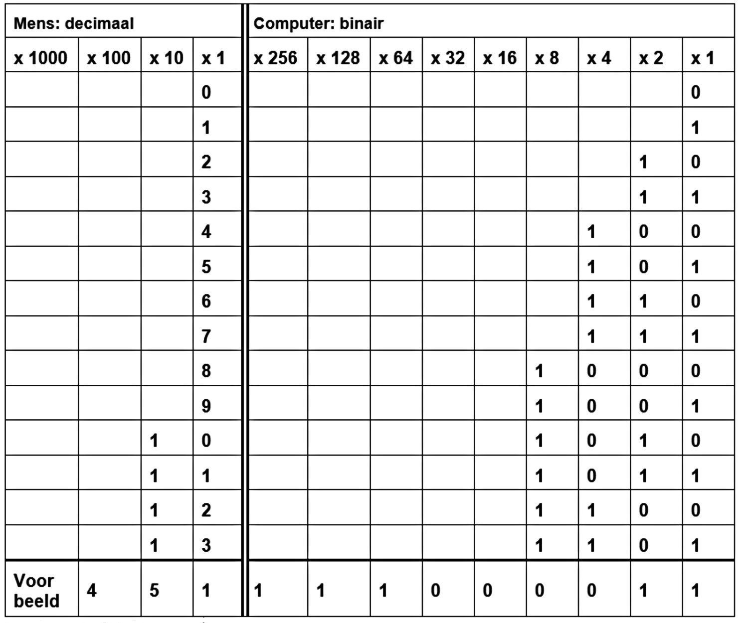
As an example, I have placed a slightly larger number in the lower part of the table; 451. You see that the computer needs many memory locations to store a decimal number in binary. For the number 451, which only takes three spaces for us, the computer needs no fewer than nine spaces. That is why a computer has to send a lot of data when processing human numbers or characters.
Binary arithmetic is also quite a bit more cumbersome.
You should only go through the following parts if you like them, otherwise you rarely or never use them.
Binary addition:
Suppose we want to add the binary numbers 00001011 and 01101010.
This actually works just like decimal addition (the ten-digit system), but with memorization for each digit:
00001011 = 11decimal
01101010 = 106 decimal
We start on the right, just like ours. 0 1 is of course 1. At the second digit we find 1 1.
That would be two, but that doesn't fit in a digit, so we say: remember 0 and 1.
At the third digit we find two zeros, which is of course zero, but we still remembered 1, so that becomes 1. The fourth digit is again 1 1, which means 0 and 1 are remembered. The fifth digit is 0 0 = 0 plus 1 of the previous digit is 1.
Digits 6 and 7 are both 1 and digit 8 = 0
So the result is 01110101 = 117 decimal
If you want, you can add decimals again and you will immediately see the agreement.
We move on to the ten because we have ten spots, the computer goes directly to the 1 because it only has one spot (light on, light off).
Now another example of multiplication.
I first give the numbers that the digits stand for:
128- 64- 32- 16- 8- 4- 2- 1
Bit 0 represents 1, bit 1 represents 2, bit 3 represents 8, bit 4 represents 16, and so on.
If we now multiply 11 by 106, the following happens:
01101010
00001011
For convenience, I put 11 at the bottom and left out the multiplication by 0.
As with us, we multiply each digit of the bottom number by the top one
The result of bit 0 = 1x106 = 01101010
The result of bit 1 = 2x106 = 212 = 11010100
The result of bit 3 = 8x106 = 848 = 1101010000
If we add all those numbers together, we get 1166 or 11x106. = 10010001110
In any case, you now understand where all those strange numbers come from when we talk about computers; they are always powers of 2!
Diode
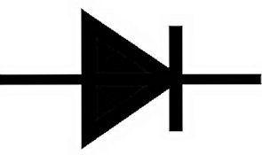
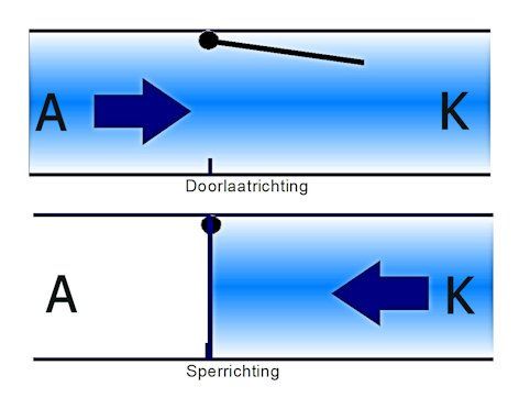
A diode is a component that only allows current to flow in one direction.
The symbol for a diode is appropriately an arrow. The left side (in this case) is called the anode, the side from which you can make an (inverted) K is called the cathode. The current flows from anode to cathode. The symbol has quite a few variations, such as an open arrow or an arrow with a line through it.
Water model of a diode
In the water model you can see a diode as a valve, the water can only flow in one direction.
When the water flows in one direction, the valve opens and allows the water to flow through.
If the water flows in the other direction, the valve closes and no water can flow. Before the valve opens, the water must already exert some pressure to lift the valve. That's exactly how it is with the diode. If we apply the voltage in the forward direction, the diode always loses some voltage to keep the valve open. In a diode this is called forward voltage (FV) or forward voltage drop. This voltage varies per type of diode from 0.2 V to 3 V. If we connect voltage the wrong way around (in reverse direction), we must take into account that the valve can only have a maximum pressure, after which it will break. The maximum reverse voltage is therefore always stated for a diode.
And finally, the valve never closes 100%, which means that a very small amount of current can flow in the reverse direction. This is called the leakage current.
There are of course many different diodes, where the reverse voltage, the forward loss voltage and the maximum current are the most important properties.
Something that is easily forgotten is that when a diode passes current it also generates power in the form of heat through the forward loss voltage. As an example: A current of 3 A flows through a diode with an FV of 1 V. The power generated is 1x3 = 3 Watt! (P=U*I). That is why we prefer to choose types with a low FV for diodes if a lot of current has to flow.
Applications of the diode
The diode is used wherever you want to convert an alternating voltage into a direct voltage (see rectifiers). Diodes are also used to prevent voltage drop in a line.
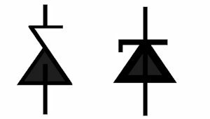
Zenerdiode
Symbols
You see a diode with a broken turning line. And that's right. If you connect a diode in reverse, it will break if the voltage becomes too high. A Zener diode is a diode that start conducting in reverse at a certain voltage without breaking down.
Of course, too much current should not flow and good current limitation is indispensable. But the nice thing is that you can create a fixed tension this way. That is why they are almost always used. Examples can be found in circuits 6,11 and 13. With Zener diodes, the Zener voltage is of course given, but also the maximum power, the minimum Zener current and the possible deviation in the voltage.
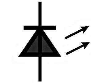
LED
A diode can also emit light and is then called an LED (light emitting diode). The symbol of an LED represents a diode that emits light. The nice thing about it is that with a diode much less energy is lost as heat. With an incandescent lamp, only 5 to 10 percent of the energy supplied is converted into light, the rest is used as heat; very unfortunate if you don't need that heat. With modern LEDs, at least 50 percent of the energy is converted into light. LEDs are available in many colors. A disadvantage is that LEDs generally have a high forward voltage.
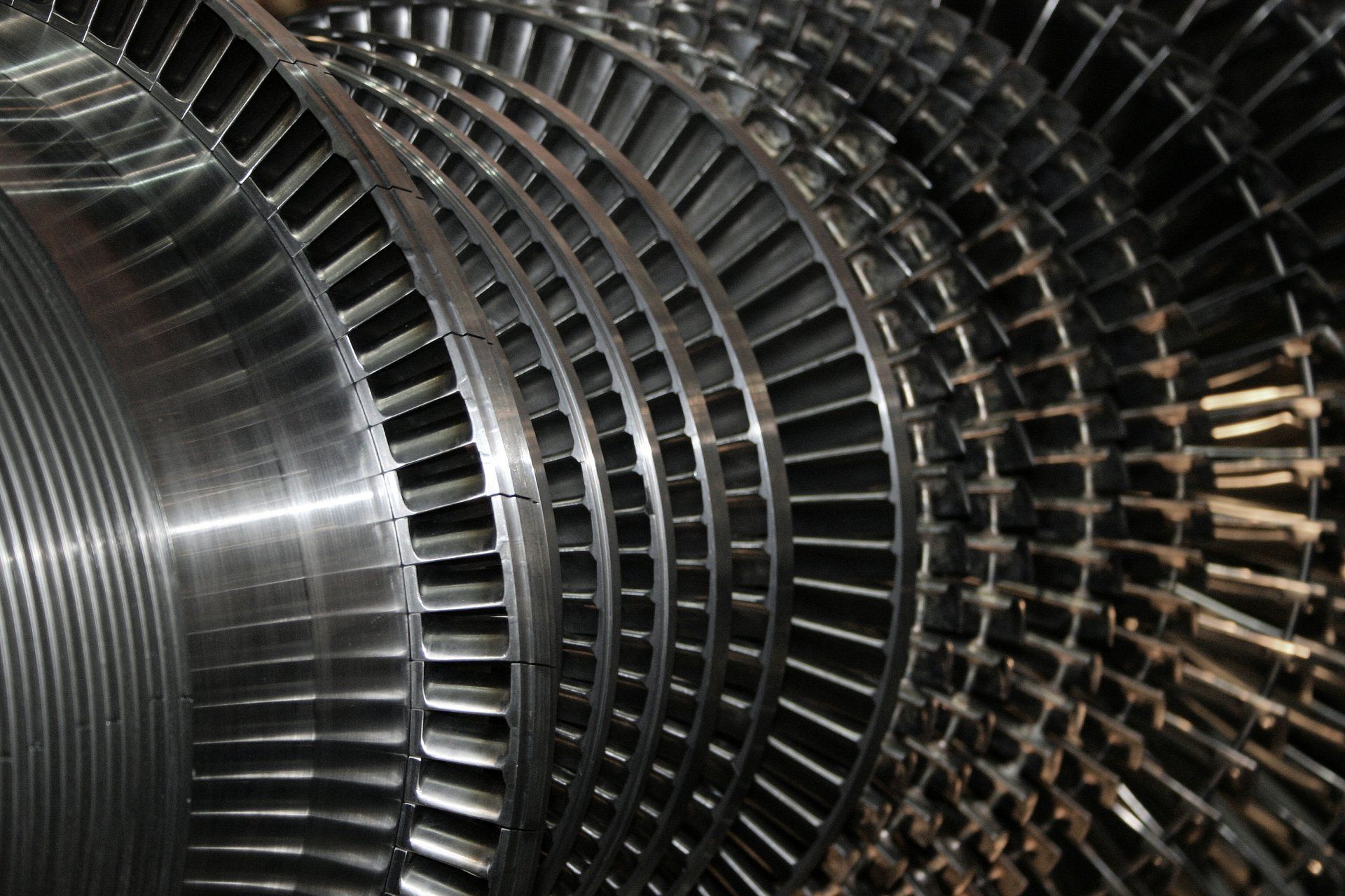
Dynamo
A dynamo is also called a generator. It is a device that converts mechanical energy into electrical energy.
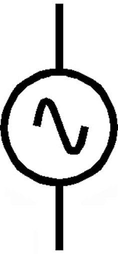
There are several symbols in use, because there are also several types of dynamos. You often see a G instead of a sinus symbol.
First read everything about the coil, you need that knowledge to understand the alternator.
A dynamo consists of a coil and a magnet with which you create magnetic waves. If you hold the coil in the undulating magnetic field, the electrons will 'roll back and forth', so that an alternating voltage is applied to the ends of the coil.
The better the coil is in the magnetic field, the better the output of the dynamo. You'll find a simple dynamo project in circuits; craft project 2 the drain pipe dynamo..
There are now many types of dynamos. The basic principle is the same for all dynamos, but thanks to many smart inventions we now have very efficient dynamos from a very small capacity to enormous capacities of up to 2 trillion watts!
symbol for a dynamo
Driving the alternator.
A dynamo must be driven, that is, something must turn the magnet or coil.
Most generators use a petrol or diesel engine for this. But there are also many generators that are driven by turbines.
A turbine is comparable to a water mill. The water or steam pressure makes the mill turn. A modern turbine is the blade turbine at the large dams. The water is very high in front of the dam.
By allowing water to flow down through the turbine from a great height, it starts to spin quickly and a dynamo can be driven. Because this does not cause any pollution, we also call this white coal. The actual source of this energy is the sun. This causes the ocean water to evaporate and be carried away as clouds by the wind. The clouds rain empty over the mountains, replenishing the water in the reservoir. The construction of a dam, however, often has far-reaching consequences for the surroundings and the environment. If there are no mountains and thus no reservoirs available, we have to generate energy differently. Fortunately, we can use wind and we can build dynamos in wind turbines. But most of our electrical energy is created using steam turbines, turbines that are driven by steam pressure. And you make steam by heating water. This heating takes place in combustion chambers, in which coal, natural gas and/or biomass are burned. This does result in significant emissions of CO2 and particulate matter, with enormous climate consequences
In a nuclear power plant, the steam pressure is created by nuclear fission. This does not release CO2 or particulate matter into the air. That is a very nice energy source! Unfortunately, up to 75% of the heat disappears in the air and in the cooling water . Other problems of a nuclear power plant are the radioactive waste, which continues to release deadly radiation (not electromagnetic radiation) for thousands of years, and the major risks in the event of accidents. The nuclear fission process can go uncontrolled in an accident, releasing enormous amounts of radioactive waste into the air or water. That is not imaginary, the disasters with the nuclear power stations in Chernobyl and Fukushima still have enormous consequences. What is less known is that more nuclear disasters have occurred, including:
Sellafield, Great Britain – 1957
Idaho Falls, Idaho, United States –1961
Jaslovské Bohunice, Czechoslovakia – 1977
Three Mile Island, United States – 1979
Ibaraki Prefecture, Japan – 1999
Nuclear energy does not cause air pollution, but there is still a lot of invention to be done before we can use nuclear energy safely.
Electromagnetic waves
Electricity and magnetism are twin brothers, where one is you will find the other. If you apply an alternating voltage to a wire, electromagnetic waves are created. Those waves fly in all directions and straight through most things. If you make a bundle of those waves, they mainly fly in one direction. The light we see also consists of electromagnetic waves. So you can see those waves very easily with a flashlight. The beam of light from your flashlight is a beam of electromagnetic waves. Electromagnetic waves, like other waves, have a wave height and a wavelength. The wave height is equal to the strength of the wave and is called amplitude. The length of the wave can be kilometers, but also smaller than a millimeter. We humans can only see three of those very small wavelengths, but there are many more that we cannot see. Electromagnetic waves are often called radio waves because they are used to transmit speech and music. Nowadays, radio waves are used for everything that we want to send without a wired connection, such as Instagram and WhatsApp.
Electromagnetic spectrum
If we neatly line up all possible frequencies of electromagnetic radiation, sorted from low to high, we call that row a spectrum. So a spectrum is the sorted collection of all possibilities. The electromagnetic spectrum is extremely large, the longest wavelength is about 100,000 km, while the shortest is about 1 trillionth of a meter.
In electronics you will not often use many values from the spectrum. It's good to know that there is more than 2.4 GHz and 5 GHz, but you certainly don't need to know the spectrum by heart. If you want to know exactly, you will find the entire spectrum here. https://en.wikipedia.org/wiki/Electromagnetic_spectrum
A strange problem.
The wave in the rope is easy to understand because the upward movement of your hand pulls up the rope particles, which then pull on the next rope particles, etc. But electromagnetic waves fly straight through space. And there are no particles to attract at all! Sound therefore cannot fly through space, you will hear nothing in the space! But the strange thing is that all electromagnetic radiation simply flies through space. This is only possible if the radiation itself consists of a stream of particles. We call these particles photons. And in physics we sometimes use the wave property and sometimes the particle property of electromagnetic radiation, whatever suits us best.
Photons? As you know, electrons move in shells around the nucleus of the atom. When an electron jumps to a lower energy shell of its atom, a very small amount of energy is released and we call that a photon. The light that flies through the vacuum consists of very small energy packets called photons .
Infrared vision: look at the TV remote control with your mobile phone camera. Choose another channel.... Thanks to your phone you can still see infrared!
Energy and power
Energy is something very special. No one actually knows exactly what it is. If you have a lot of energy, you can do many things. You need energy to move, heat, make light and much more. You could say that energy is the source of all physical work. But where does that energy come from? Nobody knows the answer. Right now we think that all the energy in the universe has always been there and always will be there. Energy comes in many forms. But not all energy is attractive and/or useful to people. Energy in the form of heat is our greatest friend, but in electronics it is almost always the greatest enemy. Since everything in electronics works thanks to the running of the electrons, heat is released everywhere. That is why all parts become warm. This is not only a loss of valuable energy, but it also causes many problems. Devices and components must always be cooled to prevent them from becoming too hot.
Energy in the form of electricity is very useful to us. All electronics work with this energy. Unfortunately, there is no natural source of electricity on Earth other than lightning. This means that we have to make electricity from other energy, for example wind energy, solar energy. Coal, gas and oil are natural energy sources. To produce electricity, it is first converted into heat (through combustion) and then into pressure to drive turbines, which in turn drive dynamos. Hydrogen is not a natural energy source, but more of a form of storage. If you want to use hydrogen as a fuel, it must first be produced using electricity.
Because the energy must first be generated at the power plant side, you must pay for that energy. That is why it is important to measure and calculate the amount of energy. We call the consumption of energy power. Power of a DC voltage is calculated by multiplying the voltage by the current. P=U*I. For an alternating voltage the following applies: P=Ueff*I (see alternating current) the unit is Watt
To calculate the amount of energy used, we multiply the power by the time that power is used: E= P*t the unit is Watt-hour
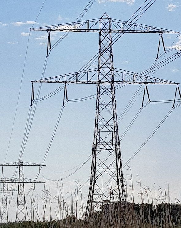
Transport of energy
Power must be transported just like other goods. The power plant generates electrical power that is transported to customers via high-voltage lines. There the high voltage is reduced to 230 VAC and transported to homes and businesses. In the house, the power enters the meter cupboard, after which it is sent to the sockets. There, the power is delivered to electrical appliances via a cable. They adjust the voltage and send the power to the components. Finally, the power is distributed across the printed circuit boards via power supplies. During all this transport, losses and disruptions occur that we must take into account.
Cable losses in energy transport
All materials, including good conductors, resist electric current. In other words: all lines have a resistance.
Now suppose we roll out a kilometer of copper wire with a total resistance of 1 Ω. We want to transmit a power of 100 Watts over that copper wire. If U = 10 V then we must supply a current of 10 A. The law of Ω teaches us that the voltage drop across 1 Ω at 10 A is equal to 10 V! At the end of the cable, all the power has been used up and there is nothing left for the user!
That is why we use a very high voltage to transport energy:
Suppose the voltage U = 1000 V. To supply 100 Watts, only 0.1 A is needed.
The loss over the cable is then 0.1x1 = 0.1 V! There is plenty left over for the user!
Ferrite
Ferrite is a ceramic material in which metals are mixed. Ceramic means that, just like porcelain, it is fired in an oven, making it very hard. Teacups are made from baked clay or baked china clay. Ceramic materials are insulators, they do not allow current to pass through. Because iron particles have been added to ferrite, it can conduct magnetic fields very well. Because it is ceramic it can be made into any shape before firing. Once fired, ferrite is very hard and very strong. Ferrite is specially made for its magnetically conductive properties. It is used in coils to strengthen the magnetic field. With ferrite you can change the value of a coil by putting in more or less ferrite. Because ferrite conducts magnetically very well, it is often used as a choke coil. High-frequency signals are short-circuited in the ferrite and therefore throttled. These inductors can be found as ferrite beads around cables and ferrite cores on printed circuit boards.

Filters
Filters are used to retain junk, so that you are left with a pure substance. Dust filters, for example, remove dust from the air, so that you can breathe clean air. In electronics, filters actually do no different. Electronic filters remove junk from your signals. For example, common clutter is noise. You can use noise filters for this. If you have too much high tones in your headphones, you filter them out. You can build many different filters with coils, resistors and capacitors. Filtering is an extensive part of electronics. Following are some simple examples.
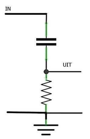
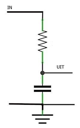
RC-filters
If you make a voltage divider with a capacitor as the 'top' resistor, the high frequencies will pass through easily, but the low frequencies will not. You've created a high-pass filter. If you replace the bottom resistor with a capacitor, all high frequencies will flow to zero and you have therefore created a low-pass filter.
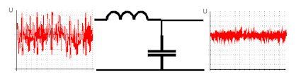
LC-filters
Coils block alternating current. The higher the frequency, the better the coil stops the alternating current. That is why coils are often used when you want to stop alternating current, such as with interference signals. In the practice of electronics we see the coil in the form of a ferrite bead, often used to suppress interference pulses. A ferrite bead is in fact a choke with a ferrite core, in which high frequency signals are choked. Nowadays, ferrite beads are available as SMC. see Ferrite
Printed wiring
In the circuits I made as a boy, all parts were soldered together with wire.
That was very messy and you quickly made mistakes. Each part had 'legs', which soldered it to a piece of wire, a solder pad, or another part.
The parts were also large and bulky.
Nowadays all that wiring is made on a plastic plate, a so-called printed circuit board or PCB for short.
Because the wiring is made via a kind of printing process, we also call it printed wiring.
Integrated circuits
Thanks to the very large, important Dutch manufacturer ASML, all parts can be made increasingly smaller. Manufacturers can therefore stick many thousands of parts together on a very small surface. We call these integrated circuits or ICs. Very large circuits will of course become hot, so that significant cooling is required. By continually lowering the operating voltage, manufacturers try to limit the power (P =U*I). Large processors, such as the I7 from Intel, have approximately 2 trillion MOSFETs on board!!! Only one simple IC is used in the example circuits. There are thousands more to discover!
Rectifiers
With an alternating voltage/current, the electrons keep running back and forth. When we make circuits, they usually use a DC voltage between 3 V and 12 V. With a DC voltage/current, the electrons always run in one direction. If we have an alternating voltage source, we must first ensure that the electrons can only run in one direction. We convert the alternating voltage into a direct voltage and of course we do this with a diode. Below you will see various rectification diagrams with explanations.
Single-phase rectification
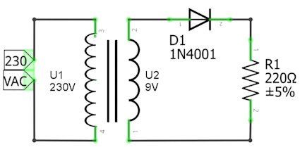
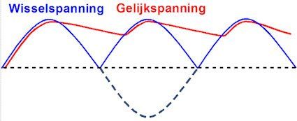
Above you see the schematic. A transformer turns 230 V alternating voltage into 9 V alternating voltage. With an alternating voltage, the current flows back and forth. If the current flows clockwise, the diode lets it pass. If the current wants to flow counterclockwise, the diode stops it.
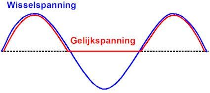
The graph shows the result of this circuit. The blue line is the voltage from the transformer. The red line is the DC voltage across the resistor. The first thing you notice is that the DC voltage becomes and remains zero when the AC voltage becomes negative. The diode then of course blocks the current through the resistor, no current through the resistor means no voltage across the resistor. Only the positive part (positive phase) of the alternating voltage is allowed through. That is why we call this single-phase rectification. If you look closely, you'll see something else that stands out. The DC voltage always remains a little lower than the AC voltage from the transformer. This is due to the forward loss voltage of the diode! As a result, not the entire alternating voltage falls across the resistor, but the voltage – FV. Most electronics will not work well on this DC voltage that keeps dropping out for a while!
Single-phase rectification with bucket capacitor
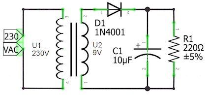
You see almost the same diagram here, except in this case a (bucket) capacitor has been placed after the diode. If the alternating voltage is positive, two currents now flow through the diode, the load current through the resistor R1, plus the charging current for the (bucket) capacitor C1. So the bucket capacitor is filled during the positive phase. If the alternating voltage is negative, the capacitor discharges (the bucket empties) via the load resistor R1. The smaller the resistance (the heavier the load) the faster the capacitor discharges.
You can see in the graph above that the voltage in the negative part of the alternating voltage drops to less than 3 V. Also not an ideal situation if your circuit needs 5 V. What can help is a larger (bucket) capacitor, but the charging current will also increase considerably. So you must choose a source (transformer) and diode that can supply and pass that large charging current.
Full-wave rectification
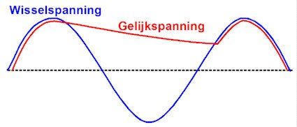
Rectification is of course much better if you could use both halves (phases) of the alternating voltage.
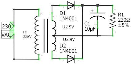
By far the most beautiful invention is therefore the solution of the full-wave rectifier. The transformer has a center tap on the output coil. The current is now sent through the load resistor using two diodes. When the current flows through the transformer to D1, it will pass the current to R1. The current returns via the center branch. D2 blocks (blocks) at that moment. If the current flows towards D2, it will pass the current to R1, while diode D1 is cut off. The (bucket) capacitor is therefore charged twice per wavelength instead of once. Therefore, the tension will also decrease less. The negative phase is thus made positive! Hence the name full-wave rectification.
Diode bridge
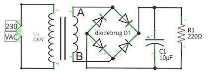
You need this circuit if the transformer does not have a center tap and you still want full-wave rectification. Two diodes are always on and two are off. Try it, how does the current flow if A is positive and B is negative? And if B is plus and A is minus? The result is almost the same as that of the previous circuit, but because the current always flows through two diodes, you are dealing with twice the forward voltage drop and double the power loss in the diodes.
Of AM-demodulator
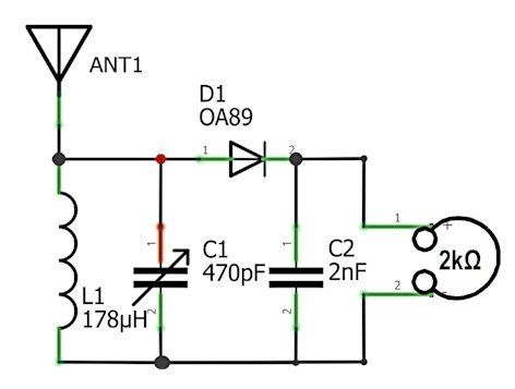
A special single-phase rectifier is the AM demodulator. It consists of a diode followed by a capacitor.
This is the diagram of a real working radio receiver. So if you want, you can recreate it.
How does it work?
The coil L1 and the adjustable capacitor C1 together form a tuned circuit (see resonance) that is connected to an antenna. The AM modulated carrier wave is rectified via diode D1, then the high frequencies are filtered out thanks to C2. The low frequencies that remain still have enough energy to directly drive a high-impedance earplug.
Historical mistake
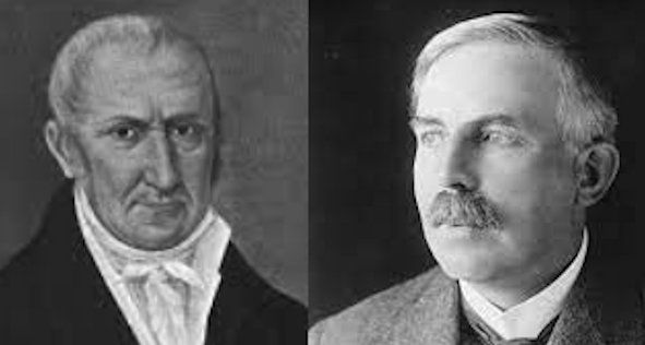
Alexander Volta invented the first zinc-copper battery in about 1800. The scientists at the time thought that the current flowed from plus to minus and therefore always opted for that. Only much later (about 1860) did a Mr. Rutherford discover that electrons have a negative charge. And... it is the electrons that can move through a conductor. The electron flow therefore runs from minus to plus! This makes no difference at all for all our calculations and we therefore continue to use the conventional current from plus to minus.
Cooling
In electronics, heat is almost always our enemy. Because electrons run through the parts, they become increasingly hot and eventually fail due to overheating.
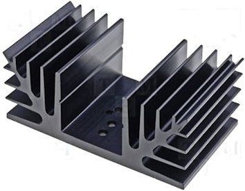
That is why a maximum power and temperature are always stated for most components. The parts lose their heat to the air that flows past them. (In special cases, water cooling is also used). Unfortunately, most parts are housed in a plastic housing. That's understandable, because you don't want the part to accidentally make contact. You also want to protect the materials that make up the part against oxidation. But plastic is not a good conductor of heat. That is why parts that have to process high power often contain metal plates in the plastic. These plates protrude outwards, allowing the part to cool much better. The larger the surface area along which the air can flow, the better the part can dissipate its heat. Therefore, you can help the part by increasing the cooling surface. Then you must of course use a material that conducts heat well, such as copper or aluminum. Aluminum is cheaper and lighter than copper, which is why it is used for heatsinks. For a heatsink it is stated how many degrees the temperature of the plate will rise per supplied power in watts. In Europe we use °C/W. The lower this value, the better the cooling capacity! Most parts state the temperature up to which they still work properly. You can of course calculate the power from the circuit. And in this way you can calculate how large the heatsink should be.
An example.
A transistor KD880 has a collector voltage of 12 V. The emitter voltage is 4 V. the current is 2 A.
The safe working temperature is 60°C. The ambient temperature is 20 °C.
12 - 4 = 8 V falls across the transistor. The power that the transistor must convert into heat is 8 V x 2 A = 16 W.
The transistor is allowed maximum
60-20 =40 °C heating.
So you need to install a cooling plate of 40/16 °C/W = 2.5 °C/W.
force
If we look closely around us, we see forces at work everywhere. All things we throw into the air fall back to earth. The earth pulls on all objects and we call that gravity. If we hold two magnets together, they will push each other away or attract each other. We call that the magnetic force.
Something that pushes or pulls on an object is called a force.
Four unexplained pullers and pushers have been found (so far):
The weak nuclear force ensures the energy exchange within the atomic nucleus.
The strong nuclear force ensures that the atomic nuclei stay together.
Gravity ensures that everything remains on the Earth and that the planets remain in their orbits.
The electromagnetic force ensures that the electrons remain around the nucleus of the atom. This power makes our electronics possible.
Forces are very mysterious, they are invisible and no one knows exactly why they exist.

Logic circuits
The word logical is used for a lot of things, but in electronics it has a very clear meaning. A logical circuit is a circuit where you can put zeros and ones into and where zeros and ones come out. A logic circuit always reacts the same to the zeros and ones you put in it. A zero and a one are always a fixed voltage. In 5 V logic, for example, this is 0 V and 5 V. Logic circuits therefore work in binary mode. There are just a few basic circuits and they are very easy to understand and apply. You can come up with a lot of fun circuits with logic circuits.
Logic gates
A gate is an arch that you can walk under, sometimes with a door in it. You enter a gate and you come out the other side. And that's exactly how it is with logic gates. There are three basic gates, with which you can make many combinations.
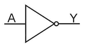
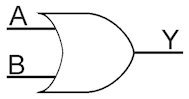
The OR gate, the AND gate and the NOT gate. The Not gate has 1 entrance and 1 exit. The exit is always opposite to the entrance. That is why the NOT gate is also called an inverter. The common emitter circuit with the NPN transistor is in fact also a NOT gate. The OR gate has two (or more) inputs. The output becomes 1 when one of the two inputs becomes 1. An OR gate is very easy to make with diodes
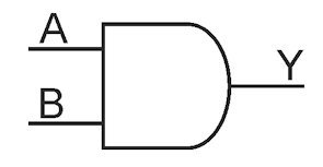
The AND gate also has two (or more) inputs. The output becomes 1 when both inputs become 1. The AND gate is also easy to make with diodes.
Leaving aside all electronic limitations, you can (logically speaking) expand the inputs of the AND gate and the OR gate indefinitely.
So you can trigger an alarm if a 1 arrives at one of the many inputs of the OR gate, for example from a glass break sensor.
Or you can ensure that you can only make a decision together. If a 1 is missing somewhere on one of the inputs of the AND gate, there will be no 1 on the output.
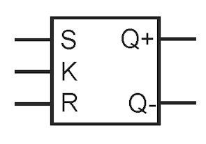
The flip-flop
In circuit 9 you will find a switch that switches every time you press a button. That's exactly what a flip flop does. A flip-flop is a logic circuit that switches the two outputs every time you operate it. Many variations of the flip-flop have been invented, but they all do the switching. Because a flip-flop has a logical hold switch, you can use it as a binary memory. Each flip-flop can remember exactly 1 bit.
There are many logic circuits for sale as integrated circuits. There are even integrated circuits (IC) whose logic functions can be selected by programming them.
Magnetism
Magnetism is a force, the why of which we do not know. What we do know is that magnetism has to do with electric force. A magnet always consists of a north pole and a south pole. Like poles repel each other and opposite poles attract each other. A magnetically sensitive material, such as iron, nickel or cobalt, also becomes magnetic when it comes into a magnetic field. The magnetic force is transmitted through magnetically sensitive materials. The object becomes a magnet that has a north pole where it touches a south pole and vice versa. If a magnetically sensitive object remains in a strong magnetic field for a long time, it also becomes a magnet
If the object is then removed from the magnetic field, it often remains magnetic. That's called residual magnetism. The object usually loses this residual magnetism after a long time. Objects that are magnetic forever are called permanent magnets. The fact that a wire, or better yet a coil, through which current flows also becomes magnetic is called electromagnetism. Electromagnetism and magnetism play a major role in our lives. Wherever electrical energy is converted into mechanical energy (including electric motor) and where mechanical energy is converted into electrical energy (including dynamo), these two forms of electromagnetism are applied. See the alternator and mono-polar motor projects for simple explanations.
Measuring
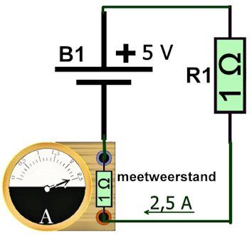
Measuring is very special because it makes invisible things visible, usually in the form of numbers and letters. In electronics we mainly measure current, voltage and resistance. To do that we need a sensor and a meter. A sensor is a component that converts a signal into an electrically measurable signal. The simplest sensor is a resistor. When we send a current through a resistor, a voltage appears across the resistor. The greater the current, the greater the voltage. We can then measure that voltage with a voltage meter and calculate the corresponding current. It is of course annoying that the measuring resistor itself also hinders the current, which means that the measurement is not completely correct. As an example, a circuit consisting of battery B1 and resistor R1. The tension that BI delivers is. 5 V., R1 = 1 Ω. You want to measure the current through this circuit. Thanks to Ohm's law, we know that the current through R1 must be equal to 5 A. Now we stick our 1 Ω sensor in the circuit. The meter only reads 2.5 A! How is that possible? Is the meter broken? No, the meter is working fine. Thanks to our measuring resistor, the total resistance in the circuit has now become 2 Ω. And 5 V divided by 2 Ω is 2.5 A. Without measuring resistor the current is 5 A with measuring resistor the current is 2.5 A. We have a measuring error of no less than 50%. We therefore choose our measuring resistance as small as possible when measuring current. The very small voltage difference across this resistor is then enormously amplified by a fixed number and only then measured. In the example we can use a measuring resistor of 0.1 Ω and amplify the signal 10x. The measurement result is then 5/1, 1 = 4.5 A. That is much better
When measuring voltage we have a similar problem. The meter also uses a resistor as a sensor. That resistance will be parallel to the resistance over which we want to measure the voltage. The total resistance therefore becomes smaller. For example, you want to measure the output voltage of a voltage divider. The voltage divider consists of R1 and R2, both 1 kΩ. The battery supplies 5V. Thanks to Ohm's law we know that the voltage across resistor R2 must be exactly 2.5 V. You connect the meter and it shows slightly less than 1.7 V! Is the meter broken? No, due to the internal resistance (sensor) of the voltmeter, there is now a resistance in parallel with R2. The total resistance there now becomes 500 Ω! The voltage is therefore only 1/3 of 5 V, which is approximately 1.7 V. Another significant measurement error thanks to the measuring resistor. That is why we use the highest possible measuring resistance when measuring voltage. Measuring resistors also have a tolerance that affects your measurement. The accuracy of your measurement therefore depends on your sensor, but also on your actual meter.
Nowadays we measure almost everything digitally. This means that we divide the time into very small steps of, for example, a millisecond and take a measurement every time a step has passed. We also call this 'taking a sample'. Each sample is represented by a number. We do this using an analogue to digital converter. By doing smart calculations (for example always taking the average of the last 10 samples) we get a value that we can display on a screen. If your meter can convert few samples per second, you will not see short voltage peaks. So you have to know exactly what the properties of your meter are to know whether the measured value corresponds somewhat to reality.
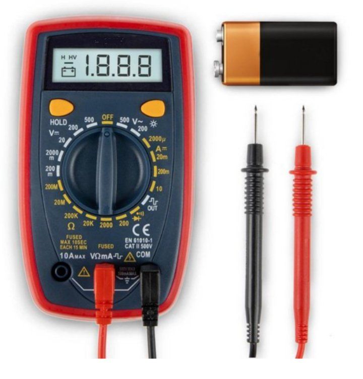
The universal meterAnd now the most commonly used meter at the moment, the universal meter, also called a multimeter. Universal because it can measure many different things and often has a number of useful tricks up its sleeve. They come in all shapes and sizes and from very cheap to very expensive. If we take into account an accuracy that we can use for our purpose, you can have an excellent universal meter for a few tens of euros.
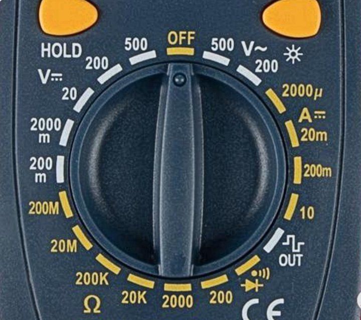
Let's take a look at such a meter. Again, there are many types and sizes, so each meter can look different. Above you will see a screen on which the selected function and the measurement result are visible. This often includes one or more keys to select additional functions. In the middle there is a rotary switch with which you choose a measuring range or function. Finally, at the bottom are the connection points for the measuring leads. What can such a meter do? We can see this conveniently from the switch with which you choose the functions. The button is now OFF, and you have to set it there every time you do not have to measure. The meter runs on a battery and if you leave it on the battery will run out! One step to the right the meter will measure alternating voltage with 500 V as a maximum. Another step to the right, the sensitivity is slightly greater and you can measure alternating voltages up to 200 V. You can then measure direct current from very accurately (2 mA full scale) up to 10 A. Please note, to measure 10 A current, the black measuring lead must be disconnected. connected to the current measuring input. This is the case with almost all multimeters. In the next step, the meter itself supplies a square wave voltage that you can use as a test signal. The next step is a whistle-through and diode test. The whistling causes the meter to beep when there is very low resistance between the measuring pins. For example, you can test cables. One pin on each side, if the meter does not whistle then there is an interruption somewhere. The diode measurement makes good use of the forward loss voltage of a diode. A good diode shows a voltage drop of between 0.3 and 1.2 V in the conducted direction and in the reverse direction the voltage is equal to the supply voltage, so much higher. The following steps let you measure a resistor in increasingly larger increments from 200 Q full scale to 200 MQ full scale. And finally, you can measure DC voltage with decreasing accuracy from 200 mV to 500 V full scale. That is already an incredible amount, for a meter that costs less than 20 euros. Let's look at the specifications, or how accurately does the meter measure? According to the specification, this meter measures DC voltage with an accuracy of ± 0.8%. Alternating voltage with an accuracy of ± 2%. Direct current with an accuracy of ± 2% and resistances with an accuracy of ± 1 to 1.5%. Measures 10 V. DC voltage, the actual voltage is somewhere between 9.84 V and 10.16 V. If you measure a DC current of 100 mA, the actual current is somewhere between 96 mA and 104 mA. It is therefore important that you know in advance how accurately you want to measure and how accurately you can measure. Bear in mind that with large values it is not useful to measure very precisely. If you want to measure the distance between Paris and Utrecht, you obviously do so in kilometers, not in millimeters. The thickness of a hair is measured in micrometers and not in kilometers. With the multimeter, the accuracy is given for the full scale reading per measuring range. In the 200 mA range the accuracy is ± 0.2% of 200mA, so ± 0.4 mA.
Microcontroller
You can compare a microcontroller with a calculator. At the heart of the calculator is a controller that controls all traffic. You can use your keyboard to pass numbers or commands to the controller. Your keyboard first translates those numbers into binary numbers, otherwise the controller will not understand them. The controller can see from the number whether it is a real number or an assignment. He then decides where to send the number. For example, he can store the number briefly in the working memory or send it to the calculation unit. If he wants to send the number back to you, he sends it to the screen. There the binary number is neatly translated into a number that you can read.
As an example, we calculate 2*3 = 6
The input is always first translated into binary numbers, the output is always translated into numbers that we can read. First you enter a 2 with the keyboard. That sends the number in binary (0010) to the controller, that stores the number in the working memory and sends it to the screen. So you will see the number 2 appear there. Now press the plus sign. The controller receives the binary command plus and places it in the working memory and on the screen. Now enter a 3 with the keyboard. That number is also sent to the controller, which puts the number back in the memory and on the screen. Finally, press the return sign. The controller receives this sign and now sends the 2, the 3 and the plus sign to the arithmetic unit. This performs the addition and returns 6 to the controller. The controller sends the 6 to the working memory and to the screen.
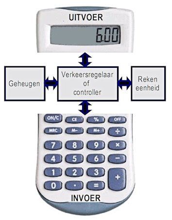
So these are the parts of a calculator:
Random access memory
A unit of account
A traffic controller or controller
Input (keyboard)
Output (display)
The working memory, the computing unit and the controller together in one house (integrated, so without a keyboard and screen) are called a microcontroller.
A microcontroller has a program memory on top of it. You can enter a whole series of commands in it (of course also binary) that will be executed by the microcontroller. When the controller reaches the end of the row, it starts again from the beginning. We call such a series of commands (instructions) a program. And writing a program is what we call programming.
In addition, a number of ports (interfaces) to the outside world are often included. The most well-known are the display interface and the keyboard interface.
Modern microcontrollers are also packed with smart solutions, especially to make them faster, more efficient and more reliable. There are many types of microcontrollers with their special properties and often their own language. You can make an incredible amount with a microcontroller. He is indispensable for an inventor. Arduino is very nice for beginners. The language is easy to learn and you can quickly make very nice things.
Modulate and demodulate.
Electromagnetic waves (radio waves) travel at the speed of light. If we succeed in packaging messages in radio waves, we can send those messages at the speed of light. Packaging a message in a light or radio wave is called modulation. The simplest modulation is 'on and off'. With a flashlight you can transmit Morse characters or ASCII codes. And even typically analog things like music or images, as long as they have been digitized first; translated into 'light on and light off'.
There are other ways to hide messages in a radio wave: amplitude modulation (AM) and frequency modulation (FM). That sounds complicated, but it really isn't! Actually, an (electromagnetic) wave only has two characteristics: the length of a complete wave part and the height. The height of the wave is called the amplitude. With amplitude modulation we change the height of the wave.
As you know, the human ear can hear frequencies from approximately 30 Hz to 20 kHz. A radio wave has very high frequencies, such as 2.4 gHz for WiFi: 2.4 billion Hz.
Sound itself travels slowly and decays quickly, but a radio wave travels super fast over enormous distances. If we vary the amplitude of that fast radio wave in the measure of the sound wave, then the sound wave travels with the radio wave.
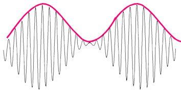
Here you can see how we can send a slower frequency by changing the amplitude of the radio wave. The radio wave is very appropriately called a carrier wave, because it carries the lower frequency with it.
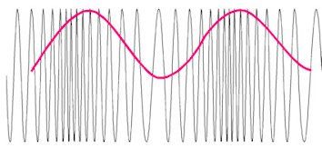
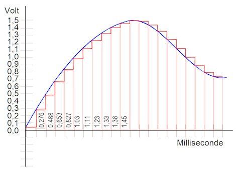
You can of course also change the length of a complete wave section. This changes the frequency of the carrier wave. You can see the result in the picture below. Here too, the low frequency is hidden in the high frequency. We call it frequency modulation or FM. The picture is very exaggerated, usually the variation is very small compared to the carrier wave.
The trick to hide the low frequency in the high frequency is called modulation. If you want to remove the low frequency again, you have to demodulate.
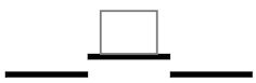
prototyping board
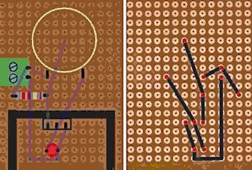
If you have made a nice, well-functioning circuit on your experimental board, you naturally want to use it somewhere. In that case, the experiment board is very inconvenient. For small circuits you can use a piece of prototyping board. This is a printed circuit board with only rows of holes. Insert the legs of the parts through the holes and solder them in place. You now use wires to make the soldered connections between the parts.
In the picture you see the circuit “the lightning machine” built on a mounting PCB. On the left the top with the parts and the cooling plate. You can faintly see the connections at the bottom shining through, just like the islands. On the right the bottom of the piece of mounting PCB with all connections. On the red dots a leg of one of the parts protrudes through the hole. So those islands are soldered. Various mounting PCBs are available for sale, with interconnected islands in rows or in groups and special models for microcontroller boards.
Morse code and ASCII code
Why the ASCII code was introduced.
Morse code consists of short and long signals in light or as a beep. In order to properly distinguish between long and short signals, it has been agreed that the long signals must be at least three times as long as the short signals. Furthermore, there must be a pause of at least 1 long signal between each character. You already understand that that is quite difficult, because one radio operator is simply faster than the other! Moreover, the number of characters is quite limited.
Morse code is error-prone and slow. This is because the difference between zero and one is a time difference that has not been precisely agreed upon. Especially if you lose count along the way, you no longer know where a new character begins. Morse code is slow because all characters are made up of long and short signals. Just look at the number 0, preferably 5 x a long signal! If you want to make more characters, they will become longer.
The ASCII code is a digital code. Each character is preceded by a pause of an agreed time. This is followed by 8 zeros or ones of an agreed time, which together form a sign. The zero is the same length as the one. Simply put, the zero is 0 V and the 1 is a fixed voltage, for example 5 V. In this way you can create 255 characters that are all exactly the same length. Because the machines are exactly in line again after each start pause, you can work with much shorter bit times. The transfer is therefore much faster and equally fast for all characters.
For comparison: The Morse code zero consists of 5 x long signals and four short pauses. That is, the time of 19 short signals.
Each character in the ASCII code consists of 8 short signals.
There are now major extensions to the ASCII code because of all the special characters, all languages with their own characters and mathematics and physics with their own characters. The code has therefore been expanded to 16 bits, which allows 65535 characters to be created.
Oscillation
You have probably experienced a microphone ringing. A nasty whistling noise drowns out all other sounds. How did that happen? The sound from the speakers ends up back in the microphone. For certain tones, the sound is amplified exactly 1 or even more times. For those tones, the sound goes round and round at maximum volume. It only stops when the circuit is interrupted. That is called oscillation. Howling is very annoying, but oscillation is widely used in electronics. To build transmitters or sirens, for example. If you send a signal at the output back to the input and the gain is at least 1, such a circuit will oscillate. Examples can be found in circuits 12, 13 and 14.
Noise
If you close your eyes and listen carefully, you will discover that the world is full of noise. You hear sounds from different sources: car traffic on the highway a little further away, an airplane passing high above you, birds chirping in the trees, the wind rustling through the leaves, and so on. We call that background noise. Your brain is perfectly capable of ignoring those sounds, so you only hear your boyfriend or girlfriend's voice. Electrical signals also contain noise. That noise, just like background noise, comes from different sources. The heat movement of the atoms causes noise from resistors, transistors and amplifiers. Switching power supplies cause a lot of switching peaks on the power supply. Electromagnetic radiation is absorbed by wires and/or print tracks. All that noise is amplified along with the actual signal. Sometimes the noise is so strong that the signal 'drowns' in it.
Noise is a major source of trouble in electronics in 99% of cases. That is why a lot of thought has been put into how to prevent or eliminate noise. That has become a profession in itself, with filters being an important part of the solution. Working completely noise-free is an illusion. Digital technology offers good protection against noise in the signal chain. After all, the signal is zero or one. The small noise signals then automatically fall by the wayside.
Yet digital technology is not invulnerable. In the signal chain itself, zero is not always exactly zero and one is not always exactly one. Therefore, the limits that apply are specified:
For example, in 5 V logic, 'less than 0.9 V' is considered zero and greater than 3.7 V is considered one.
If a signal is 1, it only becomes zero when it briefly drops below 0.9 V. If the signal is zero, it only becomes one when the voltage briefly rises above 3.7 V. The gap is called hysteresis. If your signal is 4 V, then in this case it is equal to 1. If a noise signal of -3.2 V comes along, the 1 has become a 0! The lower the voltage, the smaller the hysteresis and the more sensitive the signals to noise. And we want to reduce the voltage because of the high power that microcontrollers will otherwise use.
Smart inventors have been working on this problem for some time, so that we can work with increasingly lower supply voltages.

Switch
Usually you want to be able to turn the power in a circuit on or off. For example, you don't always leave the lamp in your room on. Fortunately, there is a switch in the wall that allows you to turn the lamp on or off. A switch usually consists of two pieces of conductive material that you can press together. Such as the momentary switch in the project "A light by your bed"
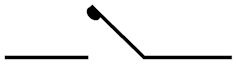
Because there are many different switches, there are also many different symbols. However, the principle is always the same. As soon as the conductors touch each other, they make contact and the circuit is closed. The conductors in a switch are therefore called contacts. So a switch has contacts that can be closed or opened. When the contacts are closed, the switch connects the connected wires to each other, but not when the contacts are open
There are many different switches. The most common are push switches, toggle switches and rotary switches. A toggle switch always remains in the position you set it to. A toggle switch is usually used to turn the light on or off. A rotary switch often has multiple decks, each with its own switching pattern. You can find them, for example, in the universal meter. Contacts can burn at high voltages and/or currents. In that case, special switches (switch rollers) are used that are filled with nitrogen or from which the air has been sucked out.
Schematic and circuit
Imagine yourself as the animal tamer at the circus. Only your animals are billions of years old, they are electrons. And you can make them do the most difficult tricks. There's nothing like jumping through a flaming hoop. To get them to do these tricks, we let the electrons flow through mazes of our own making in circuits. We place all kinds of obstacles, slides and many more electronic parts in those mazes. It is difficult to design such a maze if you cannot imagine it. That is why we make a very precise drawing of each maze. We call such a drawing a diagram. Each part has its own symbol and each connection is a line. Moreover, each part in the diagram has its own number/letter combination, so that you always know exactly which part you are talking about. You can easily draw on a piece of paper, but with large circuits this becomes difficult. With today's drawing software (CAD) you can easily draw a diagram. And immediately design printed wiring based on the diagram you have drawn. Fortunately, there is also an 'open source' project, so that you can have a good software package at your disposal for free. https://kicad-pcb.org/.
Serial and parallel
Resistors in series
If you connect resistors one after the other; in series, the total resistance increases, namely the sum of all resistances.

Series: R-total = R1 R2 R3 (and so on)
Together 16 Ω (remember: always larger than the largest)
Resistors in parallel
If you connect resistors next to each other, in parallel, the total resistance becomes smaller and smaller.
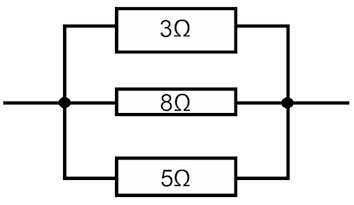
You can calculate the total resistance with the following formula:
Parallel: 1/R-total = 1/R1 1/R2 1/R3 and so on.
Together 2.6 Ω (remember: always smaller than the smallest)
The black lines are the connecting wires and have 0 Ω resistance. In the drawings I have drawn the highest resistance as the narrowest tube. In real electrical schematic drawings, the blocks are all the same and the value is simply stated next to or in it.

Series and parallel connection of capacitors
Condensator in series
If you stick capacitors together (in series), the capacitance becomes smaller and the alternating current resistance becomes larger.
In series connection, the replacement value consists of the addition of the reversed values:
1/C-total = 1/C1 1/C2 1/C3 (and so on)
(That is just the opposite of the resistance)
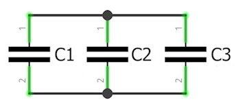
Capacitors in parallel
If you connect capacitors in parallel, the capacitance increases. This is easy to understand because the AC voltage across the capacitors is the same everywhere and the plate area increases every time you connect an additional capacitor in parallel.
For the replacement capacity C of the parallel connected capacitors C1 to Cn, we add the capacitances of the capacitors together.
C-total = C1 C2 C3 (and so on)
Series and parallel connection of coils
Inductors are not as easy to calculate as resistors and capacitors. Coils are sensitive to magnetic fields, but they also create them when you pass current through them!
So if you place coils one behind the other or next to each other, they will always feel each other's magnetic field.
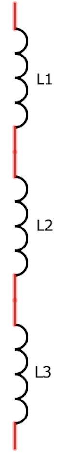
Coils in series
Because the self-inductance of a coil is directly proportional to the number of turns, the formula for a series connection is simple:
L-total = L1 L2 L3 and so on.
The DC resistance also adds up, but the parasitic capacitance actually decreases. But due to the magnetic fields of the coils connected in series, the result of the formula is not accurate.
Coils in parallel
There are no simple calculation rules for connecting coils in parallel. Coils owe their alternating current resistance to the fact that they have to build up a magnetic field that is consistent with the current flowing through the coil. Unfortunately, that magnetic field also affects the coils that are placed next to a coil. If we forget that for a moment, you could use the following formula:
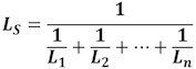
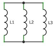
What is also possible is that the coils lie completely in each other's magnetic field. If the direction of their fields is the same, the parallel connection will have no consequences for the inductance. The direct current resistance does of course decrease.
If the direction of their fields is opposite, they cancel each other's inductance! If they are also of different values, currents will flow between them, which can cause them to become hot and break! It is therefore important to measure series and parallel coils in practice.
SMC of SMD
The old parts I used in the past are often large and bulky. Modern parts for a PCB are much smaller. They are soldered directly to the surface of the printed circuit board and are therefore called 'surface mounted components' or also “surface mounted devices”.


There are still parts with legs.
Fortunately, because for us inventors it is very easy to quickly put something together on an experimental board. Huh, an experiment board? What is that?
Experimental plates are made especially for hobbyists, which are thick plastic plates with holes under which copper springs are located. These springs are connected to each other in rows, so that you can quickly assemble a circuit. The official name is breadboard and you are definitely going to need one, luckily they are not expensive. In the photo you see a breadboard with 2 x 20 rows of 5, connected to each other, holes and below and above power lines always divided into groups of 5. In the top part of the drawing I have shown with lines how the copper springs are connected. :
In row 1, a, b, c, d and e are connected. And also f, g, h, i and j. This is exactly the same for every row. At the red and blue power lines you can see that 5 holes are connected one below the other. As an example: The thick red wire from the left is connected to the resistor via the plus power pins. The other side of the resistor is connected to the LED via row 8. The other leg of the LED is in row 10. Row ten is connected to the negative power pins with a blue wire and the thick blue wire is connected to that. If you connect a battery to the red and blue wire, the LED will turn on.
Soldering
Metals become liquid when you heat them. Metals do not all have the same melting point. Copper only melts at 1080 °C. Silver melts at 960 °C and tin at 230 °C. When you mix metals (called alloying), the mixture (alloy) does not have a precise melting point, but first becomes viscous and then increasingly liquid as the temperature continues to rise. Nowadays we use a mixture of tin and silver as solder. You can liquefy solder with a soldering iron (a heated point of metal with a high melting point). If you hold that liquid metal mixture against another metal with a higher melting point, an alloy is also formed at the interface. If you then allow the metals to cool at rest, they will be mechanically and electrically well bonded together.
We use this when we want to solder parts together or on a printed circuit board. Tin/silver solder can be easily processed at approximately 380°C. Unfortunately, your soldering iron also loses atoms to the hot liquid, so that it is slowly 'eaten'. Furthermore, liquid metal can very easily combine with the oxygen in the air (oxidize). Metal oxides conduct heat and electricity very poorly, so we cannot use them. That is why an anti-oxidant (flux) is added to the solder. In modern solder, this agent is already in the solder wire. It is useful to look at an online soldering course or demonstration. This way you quickly understand how to do it. Allowing good flow and not using too much solder are probably two important instructions.
Rinse
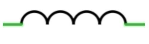
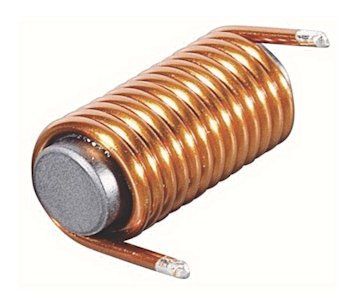
A coil is a component that consists of a conductive wire wrapped around a coil shape with or without a core. To understand a coil, we have to go back to physics class. From this we know that a magnetic field is created around a wire through which current flows.
By wrapping the wire around a coil body, the windings strengthen each other's magnetic field in such a way that the coil generates a magnetic north pole at one end and of course the south pole at the other end (depending on the direction of current).
Coils also come in many shapes and sizes and with different core materials, but the basic principle of the coil is always the same: a coil always counteracts a change in current. And that is because the increasing current in a coil causes an increasing magnetic field, i.e. a magnetic wave.
The coil is therefore in a magnetic wave that it produces itself. However, that magnetic wave creates a countercurrent in the coil. Or to stay in visual language: the magnetic wave causes the coil to lean to the other side, so that the electrons want to roll back. Any changing current through a coil causes a changing magnetic field that initiates opposing electron movement. We call that self-induction.
Water model of the coil
In the water model, a coil is represented as a paddle wheel that drives a flywheel.
a) Initially the wheel is at rest.
b) If we now connect water pressure, the wheel will first offer a very high resistance. Slowly the wheel starts to turn and once it turns, it will become easier to turn faster and faster.
c) Until the water is almost no longer bothered by the wheel.
d) If we now reverse the direction of the water pressure, the paddle wheel will first continue to rotate and thus make the water pressure even higher. The wheel will now reduce speed due to the counter pressure and eventually come to a stop.
e) Then the wheel starts turning in the other direction. at first slowly but then faster and faster.
f) until the water is almost no longer an obstacle.
You see that voltage is first applied to the coil and only then does current flow. We call this lag. With an alternating voltage, the current through the coil lags 90° behind the voltage. An inductor does exactly the opposite of a capacitor!
A coil can also store energy thanks to the flywheel. And a coil counteracts change due to self-induction. This makes the coil a good conductor for direct current, but a resistance for alternating current. The value of a coil is expressed in Henry. The coil is indicated by the capital letter L. The degree to which a coil hinders an alternating current is called impedance with the symbol ZL. Impedance corresponds to alternating current resistance and therefore has ohms as its unit. You can calculate the impedance of a coil using the following formula:

The impedance of a coil therefore increases as the frequency of the alternating voltage increases. In practice, coils also have an ohmic wire resistance.
Applications of coils
Coils are used in filters, for the conversion of electrical energy to mechanical energy and as energy storage.
In filters we use the fact that coils offer a high resistance to alternating current and that this resistance increases as the frequency increases (see filters)
Converting electrical energy into mechanical energy. Once the current flows, the coil becomes a powerful magnet that can attract plungers, pull levers or move itself within a magnetic field. You may already know these applications as solenoids, relays, speakers, etc.
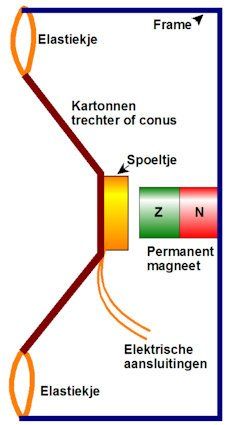
Speaker
A loudspeaker is perhaps the nicest invention with a coil.
It works as follows:
If you send an alternating voltage through a coil, it becomes a magnet whose north and south poles keep changing. If we suspend the coil springily in the field of a permanent magnet, it will be alternately attracted or repelled by the permanent magnet. The coil moves back and forth through the coil at the frequency of the alternating current!
We stick a funnel made of light cardboard on the spool, the so-called cone, which then moves back and forth with the spool. The vibration of the cone sets the air in motion, and we perceive vibrating air as sound. At least if the frequency is in the audible range for us. The principle of the modern loudspeaker is still the same, but many inventions have been made to ensure that the sound sounds as natural as possible. The speaker symbol looks like a small speaker. The resistance and maximum power are often stated. Loudspeaker data sheets often include a graph showing which tones are reproduced best.
Microphone
The nice thing is that the principle also works the other way around. If you vibrate the cone using sound (for example by singing to it), the coil will vibrate along with it. The coil is located in the magnetic field of the permanent magnet, causing the electrons in the coil to roll back and forth in time with the sound. In other words, an alternating voltage appears on the coil with the frequency of the sound. Such a sound sensor is called a microphone. To make the sound sound as natural as possible, a good microphone is constructed very differently, but the principle is completely the same. So you can really use a speaker as a microphone, although the sound quality is not very good.
Piezo
You can also make good speakers and microphones using the principle of a condenser. And nowadays materials have been invented that shrink or expand immediately when you apply a positive or negative voltage. Piezo crystals, for example. This allows you to make tiny microphones and speakers that still sound reasonable. Three guesses what they are in.
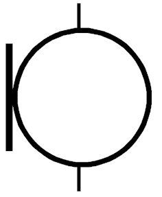
Coil as Relay
Another good example is a relay. A relay is a switch that is electrically operated. A relay consists of a coil, an armature and two spring contacts. If we send current through the coil, it becomes a strong magnet. That magnet pulls the armature down. The other side of the armature then presses the spring contacts against each other; the switch is closed. When you turn off the power, the armature is no longer attracted to the coil. The spring contacts spring back and no longer make contact; the switch is open.
The symbol for a relay consists of the symbol of a coil connected by a dotted line to one or more contacts.

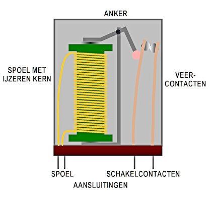
Storage of energy in a coil
Once the current flows through a coil, it will continue if the line is interrupted, because the wheel still has momentum. The stored energy is released as a voltage peak. If the coil is suddenly disconnected, this can lead to high energy pulses! In the case of a relay, you obviously don't want that, as it can destroy the electronics that switch the relay.
A freewheeling diode solves this problem. See the image below.
1 the relay is energized and a current flows through the coil from positive to negative. The diode is in the reverse direction.
2. The relay is switched off. The current in the coil continues to flow for a while and is short-circuited via the diode.
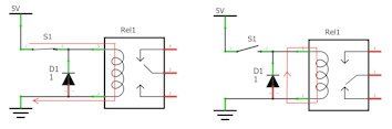
Switching power supply with energy storage in a coil.
We can also take advantage of this property of the coil. A switching power supply makes good use of this property. As an example, the operation of a switching bucket power supply (buck regulator)
1. the switch is closed and the coil starts up. An increasing current flows through the load resistor. The diode is turned off.
2. The switch is open and the coil can deliver the stored energy to the load resistor thanks to the diode. The diode is conducting. A decreasing current flows through the load resistor. By choosing the switching times carefully and absorbing the voltage variations with a capacitor, we can determine the output voltage.
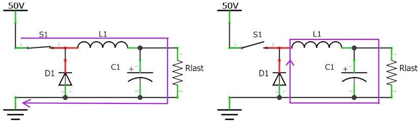
Transformer
We reduce an alternating voltage with a transformer, two very well-coupled coils of different values. The symbol of a transformer consists of two coils lying flush against each other, often with one or two lines in between to indicate that it contains a (soft iron) core. Because there are many different transformers, with many or few windings, you will also find many variations on the symbol. A winding is exactly one wire loop of a coil. By changing the number of windings we change the voltage and maximum current of the transformer coils.
As an example, a mains transformer with three output voltages (6V, 9V and 12V) and a maximum power of 12V, 0.5 ampere. You can see the symbol next to this. A mains transformer has many thin windings on the primary side of the mains. On the secondary side one or more coils with a thick wire and relatively few windings. Apart from losses of energy (in heat), the primary power is equal to the secondary power. A primary coil of 230 VAC at 1 ampere can therefore supply almost 230 Watts at the output. A good transformer is quite efficient up to 97%.
Transistor in MOSFET
Transistor and (mos)fet are semiconductors with three connections. A large current can flow between two of those connections, the third connection serves to regulate that current. Transistor and mosfet have a completely different internal structure. Both have their pros and cons. In transistors the three connections are called; Collector, Emitter and Base. The basis is the control input, the main current runs between Collector and Emitter.
With the Mosfet the connections are called Drain, Source and Gate. The gate is the control input, the main current flows between drain and source
See the symbols opposite.
remember: transistor = current controlled mosfet = voltage controlled
There are two types of each, an N-type and a P-type. In the NPN transistor, the emitter is the output of the large line and the collector is the input. With the PNP transistor it is the other way around, which you can easily see from the direction of the emitter arrow.
With the Mosfet, the current flows from drain to source with the N-channel type and from source to drain with the P-channel type.
De NPN transistor
On the left you see the water model of an NPN transistor. The main channel is closed with a plate with holes. There is a rubber flap with holes on the plate, but offset in such a way that the channel is closed. When we now blow water through the thin pipe on the side, the rubber flap comes loose from the metal plate and water can flow through the main pipe. The more water you send through the side entrance, the greater the distance between the rubber flap and the metal plate becomes, so that much more water can flow. At a certain point the cloth and plate are so far apart that the maximum current flows; more power steering from the side makes no sense. When I had completed the water model, there would also be a check valve at the bottom of the transistor, like in the diode. The water cannot flow back. Since the transistor is a controllable diode, it also has a forward voltage drop between the base and the emitter. This voltage drop varies from 0.5 to 0.9 V. In our sums we always assume 0.7 V in the formula: VB – VE = 0.7 V
The transistor is therefore a large diode tube that you can open by allowing current to flow into the large tube through a small tube. The collector is the entrance to the large tube. The emitter is the exit of the large tube. This is where the current comes from that enters via the collector and the base. In the formula: IE = IB IC
How far the large tube opens due to the small auxiliary current through the base varies per type of transistor. We call that the current amplification factor and the symbol is ß. By multiplying the base current by the current gain you get the corresponding collector current. In the formula: IC = ß 0.2 V to as much as 0.5 V. With large currents, a transistor therefore becomes quite hot, and much hotter if it is only half open. That is why a transistor is then cooled. The properties of a transistor are recorded on a data sheet by the manufacturer. There you will find the maximum voltage between collector and emitter, the maximum current, the maximum power and the gain factor of the transistor. The maximum frequency at which the transistor still works is often also mentioned.
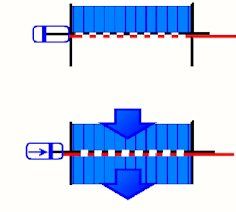
Of N-MOSFET
With the N mosfet, two grids lie on top of each other, precisely in such a way that they close each other's holes. So no water can flow. If I now apply pressure through the side on the top grille, it slides to the side and the holes are exposed. The further I slide, the more water can flow. Finally, the holes are exactly above each other and the maximum current has been reached. When I stop applying pressure, the top plate springs back and the power shuts off. The current cannot flow back with the MOSFET either, but the MOSFET does not have a built-in diode. This also means that there is no fixed threshold voltage. On the contrary, you should think of the mosfet as an adjustable current source. Each gate voltage has a fixed channel opening. The control voltage of mosfets is therefore variable and ranges from the minimum gate voltage to 10 or more volts. The Mosfet requires minimal pressure to slide the valve open. This tension varies widely. For a Mosfet, the minimum gate voltage VGS is therefore stated at which it will still open. Please note: this can also be 10 V or more. If the gate voltage rises above VGS, the mosfet will open further as the gate voltage increases. At a certain voltage the mosfet is fully open. A very small internal resistance remains, with most mosfets a few to tens of mΩ. That is why mosfets are very suitable for switching large currents. The voltage loss across the small internal resistance is very small, so is the dissipated power. As an example, a mosfet with an ON resistance of 12 mΩ has a voltage loss of 10x0.012 at 10 A. = 0.12 V so a power of 1.2 Watts. A transistor with a 0.3 V loss would produce no less than 3 Watts of heat. You can also find all important information on the data sheet for mosfets.
It is now clear to you that there are many variations of all parts. This also applies to the BJT and the MOSFET. Fortunately, there are many transitors and mosfets that are pretty much universal and are the most commonly used.
Transistors and MOSFETs play a major role in electronics; virtually everything is built with it. You can use them as switches, memory elements, amplifiers and much more. You will encounter a number of practical applications in circuits.
Basis transistorschakelingen
There are three basic circuit diagrams for transistors. The common emitter circuit or GES, the common base circuit or GBS and the common collector circuit or GCS. The most commonly used is the common emitter circuit and is therefore explained further below.
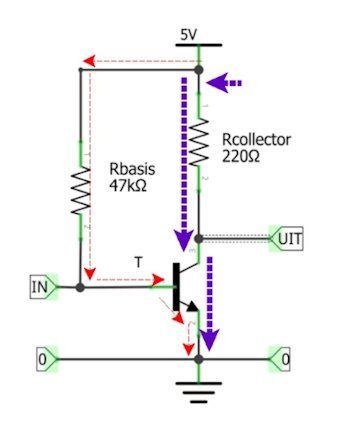
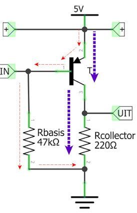
The common emitter circuitHere you see an ordinary NPN transistor in conduction. There are 2 circuits: the base-emitter circuit (the red arrows) and the collector-emitter circuit (the purple arrows). The base is supplied with power via R1. Ohm's law applies to R1, so the current through R1 (and the base) is equal to 4.3/47000 = 0.09 mA. The collector current is then ßX0.09 mA = 200x0.09 mA = 18 mA. The emitter current is then of course 18 0.09 = 18.09 mA. The collector resistance is 0.018*220 = 3.96 V (Ω's law U = I*R). The power supply pushes the current through the circuits, so the current flows through the power supply back from 0 to 5 V. This circuit can be used for many fun inventions.
Because the emitter is at zero, it is used for both the input and the output, hence the name: 'common emitter circuit'.
Here you see the PNP transistor in common emitter circuit. It takes some getting used to, but as you can see, the transistor does everything the same as the NPN transistor, only exactly in reverse. The emitter is connected directly to the 5 V. The 5 V line is now the common line for input and output. The base is always 0.7 V lower than the emitter and the currents are therefore opposite. You will discover that combining NPN and PNP offers many possibilities.
The power line is a virtual zero for all signals. The power supply ensures that the supply voltage always remains the same (5 V in the example). So if an alternating voltage signal arrives on the power supply line, it will be short-circuited to zero via the power supply.
If you apply an alternating current variation to the input of a GES (the base), it will appear in reverse at the output (the collector). So the GES is an inverter!
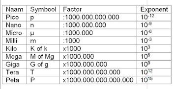
Multiplication factor
Electronics often works with very large and very small numbers. That is why multiplication factors are used. You have known some of them for a long time, such as kilo for 1000 times. A kilogram is 1000 grams, a kilometer is 1000 meters and a kilo-Ω (kΩ) is 1000 Ω. Here you will find a handy overview of all factors used in electronics. The custom is to paste the symbol directly in front of the unit name. 1 µH = 10-6 Henry, 1 MgΩ = 106 Ω, and so on.
Resistance
As the name suggests, resistors resist current, in other words resistors hinder current. the greater the value of the resistance, the more difficult it is for current to pass through.
The value is given in the unit Ohm, usually abbreviated to the Greek omega sign: Ω. Here you see the European and American symbol for resistance. In the diagram the value is stated next to or in the resistor. A resistor has a value of 1 Ω if exactly 1 A of current flows when you apply exactly 1 V voltage across the resistor. Nowadays resistors can be made very precisely, with margins of error of less than 0.1%!
There are many different types of resistors, depending on the application.
You will use the models shown here the most. On the left the normal resistor with legs and on the right an SMD resistor that can be soldered directly to the printed circuit board thanks to the metal edges.
The water model of resistance
This is the simplest water model: compare a resistor with a pipe through which water flows. The narrower the pipe, the more difficult it is for water to flow through it and therefore the higher the resistance value.
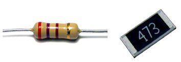
Wet van Ohm
Current will only flow through the resistor if a voltage is applied to the pins. The more voltage, the more current will flow, but the greater the resistance, the less current will flow.
You can immediately see this in Ohm's law.
Greater voltage means greater current, greater resistance means lesser current.
Conversely, we also know what voltage is across a resistor if we know the current and resistance: U = I x R.
And finally, we can calculate resistance if we know the voltage and current. R = U/I
This applies to any resistor anywhere in a circuit!
Power of a resistor
Resistors convert the voltage difference into power in the form of heat. A resistor becomes warmer as the voltage increases and also as the current increases.
You can immediately see this in the formula for the power P:
P = U x I
Where P is the generated power in Watts, U is the voltage across the resistor in Volts and I is the current through the resistor in A.
The heat that is generated must be properly dissipated, otherwise the resistance will become too hot and could break.
Always ensure that you have a resistor of the correct power and sufficient cooling.
Basic applications of resistance
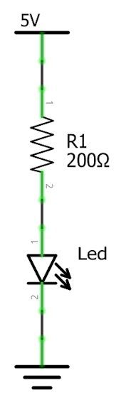
Current limitation
Resistors are often used in series with other components to limit the current through that component. An example of this is the following LED control.
During conduction, a voltage (forward voltage) of 1 V falls across this LED. The LED works best at a current of 20 mA. The voltage across the resistor is therefore 4 V when current flows through the LED. We want to limit the current to 20 mA, the resistance value now follows from Ω's law:
R=U/I
The resistance must therefore be: 4: 0.02 = 200 Ω
Always ensure proper current limitation to protect your components. Keep in mind that the power is now largely generated in the resistance. In the example, the power in the resistor is 4 x 0.02 = 0.08 Watt.
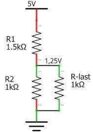
Voltage divider
With resistors we can divide a voltage into several smaller voltages. Here you see a simple voltage divider.
The input voltage is divided into U1 and U2 by the resistors. You can calculate this with the following formulas;
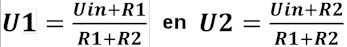
It becomes a bit more difficult if you want to connect a circuit to the voltage U2 that may/must operate on U2. Of course, that circuit also uses current and is therefore in fact an extra resistor that we also call a load resistor or Rlast for short. The bottom resistor now consists of the parallel connection of R2 and RLast.
This makes the formulas a little more complicated, but if you look closely, it's not that bad, right?
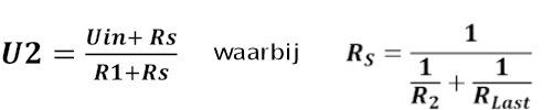
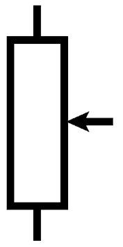
Potentiometer
A potentiometer is an adjustable voltage divider. It is made of one large resistor over which a contact slides. You can immediately see that in the symbol. If you turn the slider up, the upper resistance becomes smaller and the lower resistance increases and vice versa.
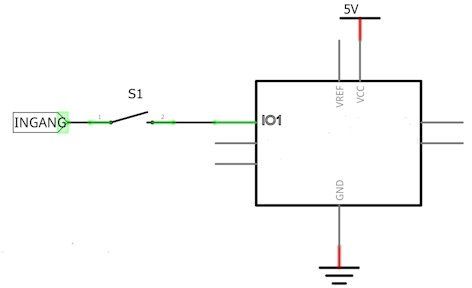
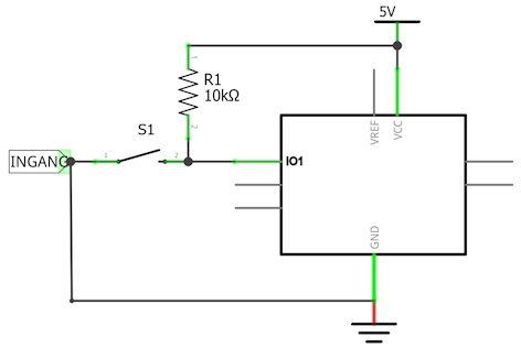
Anti “floating” resistance
If a copper wire is not connected to anything, you never know what voltage is on it. Such a 'floating' pipe is very sensitive to malfunctions. So you certainly don't want any loose ends in your circuits. Yet that happens easier than you think. Just look at this very simple circuit of 1 single switch:
What is actually the voltage on IO1 when the switch is open? The line from the switch to P 'floats' and can therefore assume any value! Electrons can simply jump into the wire if there is a surplus somewhere or induction voltages can occur.
Of course you don't want that at all!
That is why we ensure that a pipe is always connected to something. We do this by connecting the line with a resistor to a known voltage, usually the supply voltage or neutral.
If we increase the voltage, we also call that resistance a pull-up resistance. If we pull to zero, it is called a pull-down resistor.
In the circuit shown here we know exactly what the voltage at P is, thanks to the pull-up resistor: 5 V. When the switch closes, P becomes 0V.
The choice of the value of such a resistor is always a compromise. The resistor reduces the total resistance of the circuit and therefore also uses energy. A resistor of 10 Ω in the example would make the input very insensitive to interference, but when the switch is closed it requires no less than 0.5 A and therefore 2.5 Watt! A common value for a 5 V supply is 10 kΩ, for a 3 V supply 3.3 kΩ. Make sure that all nodes always have a value.
Color code for resistors.
The standard resistors have four rings. One of those rings is at a greater distance, that is the tolerance ring.
Hold it to the right. The color values run from 0 to 9, black = 0, brown = 1, red = 2, orange = 3, yellow = 4, green = 5, blue = 6, purple = 7, gray = 8 and white = 9
We count from the left: Write down the number per ring. Standard resistors have ring 1, ring 2, a number of zeros in ring 3 and a tolerance.
The upper standard resistance is therefore 470 Ω with a tolerance of 2%
Precision resistors have an extra ring: ring 1, ring 2, ring 3, a number of zeros in ring 4 and a tolerance.
The lower precision resistance is therefore 39000 Ω, that is 39 kΩ with a tolerance of 2%
If the tolerance ring is missing (blank), the resistor has a tolerance of ± 20%. Now a resistor may deviate a little bit, but it is better not to use these resistors.
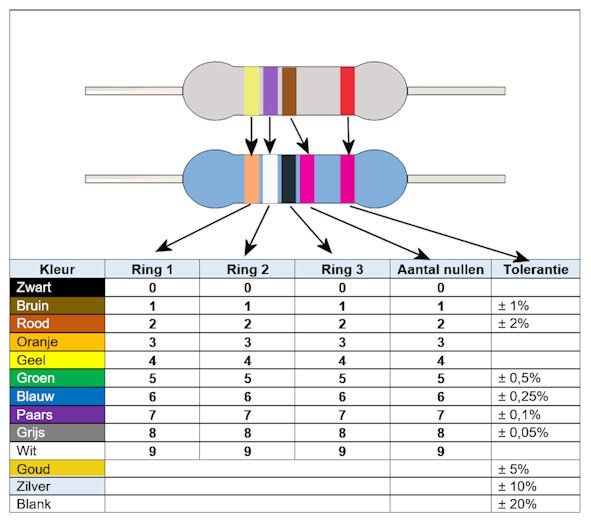
Alternating voltage
With an alternating voltage, each pole is alternately plus and minus. The electrons therefore run back and forth.
Although alternating current can take many forms, it is usually sinusoidal. The number of changes per second is called the frequency f, expressed in Hz. Because alternating voltage is constantly changing, we need to know exactly what the alternating voltage is doing at one moment during measurements. We call that the phase. The phase is divided into 360 degrees. Then the wave starts again. At 180 degrees the voltage across the poles is exactly 0 V, at 90 degrees the voltage is maximum. the distance between 0 and 360 degrees is exactly 1 wavelength with λ as the symbol and meter as the unit. The other units and values for alternating current are the same as those for direct voltage. Voltage has the symbol U and the unit Volt. Current has the symbol I and the unit A. In Europe, for example, 230V AC at 50 Hz is supplied via the socket. (AC stands for alternating current)
The effective value
An alternating voltage constantly changes polarity. The voltage on the poles continually changes between 0 V and the maximum voltage. The maximum voltage is called the top-to-top voltage. The amount of power that an alternating voltage produces naturally also changes between 0 and the top-to-top energy. If we compare a direct voltage and an alternating voltage, it is noticeable that an alternating voltage is lower than the direct voltage for a large part of the time. A direct voltage with the same value as the peak voltage of an alternating voltage will therefore supply much more power. To deliver the same power, we need an alternating voltage with a higher peak-to-peak voltage. That is why we usually talk about the effective value of alternating voltage (and current). The effective value of an alternating current is the value of the direct voltage that supplies the same power as the alternating voltage. See the formula opposite. The top-to-top tension is therefore much higher than the effective tension. For example, the top-to-top voltage of our 230 VAC(eff) is no less than ±325 V
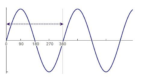
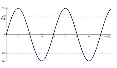
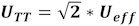
Alternating voltage has the advantage that it can be used for inductive transfer (see coil and transformer). This makes it easy to transform alternating voltage into other voltages. And that is very necessary for the transport of energy (see cable losses).
With alternating current we can also create electromagnetic waves, which travel at the speed of light through space and air, among other things. That is the basis of (almost) all wireless data transfer, such as WiFi.
The propagation speed of the current in a substance (such as iron or copper) has the symbol v and the unit meters per second.
You can find the wavelength by dividing the propagation speed by the number of vibrations per second:
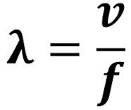
Since the speed of propagation through different substances is different, so the wavelength changes as the vibration moves through another substance. This also applies to electromagnetic waves.
Fuse
A fuse is used to protect a circuit and/or power supply against excessive current. The old-fashioned fuse consists of a glass tube containing a very thin silver wire. At a certain current, the wire burns and no more current can flow. You can find this in the symbol. It consists of a rectangle with a melting wire in it. The maximum current value is stated there. In this case 1 ampere. The T stands for slow, which means that this fuse does not blow with very short overloads, as long as they are not too large. If it says F (fast), the fuse will blow immediately.
Nowadays many new materials have been discovered with which fuses can be made. For example, there are self-resetting fuses that have a very high resistance value in the event of overload. When the overload disappears, this fuse again assumes a very low resistance value.
Solar cell
You already knew that you can make light with electricity. But it is also possible to convert light energy back into electrical energy. And we have an inexhaustible source of energy in the sky: the sun. There are many ways to use solar energy, but the solar cell is an electronic way. Solar cells are made in such a way that incident sunlight causes a voltage on the connections of the solar cell. Unfortunately, the return is not very high. A maximum of 20% of the incident light is (currently) converted into electricity. But a lot of people are working on that. One invention after another ensures that the return is increasingly higher. How exactly a solar cell works is so complicated that the famous scientist Albert Einstein had to be involved to explain it. For us it is enough for the time being that we know it works. The cheap Chinese garden lights all contain solar cells. These lights rust quickly and are then replaced after a year. A shame for the environment, but good for us: the solar cells are usually still fine to use!