


Everyone is an inventor, and especially you!!
Here you'll find circuits you can copy and use to create your own. If you've come up with a fun and well-functioning circuit, feel free to submit it. If we approve it, it will be posted on the site with your name attached. This way, you'll also help others with great ideas.
Disclaimer: We have done our utmost to test all circuits for functionality and safety before publication. However, any reconstruction is entirely at your own risk. We are not liable for any damage that may result from replicating the published circuits.
Good luck with these projects!


A simple dynamo to make yourself
For this project you will need:
- 10cm PVC pipe with a diameter of 5cm.
- Two spools of 60 m 0.25 mm copper wire, available as AWG30, at www.magnetenkopen.nl.
- 15 cm of welding wire or 2.5 mm thick iron wire.
- 2x nylon spacer bush 6mm long and a 2.5mm hole.
- contact adhesive such as Bisontix.
- glue for hard PVC.
- Two neodymium block magnets measuring 30x20x5mm with a holding force of 10kg. Available at www.magnetenkopen.nl under number: Block NM-30-20-5.
- 2x LED of your choice.
- 1 resistor of 33 ohms.
As tools you will need
- mitre box
- hacksaw
- small file
- tang
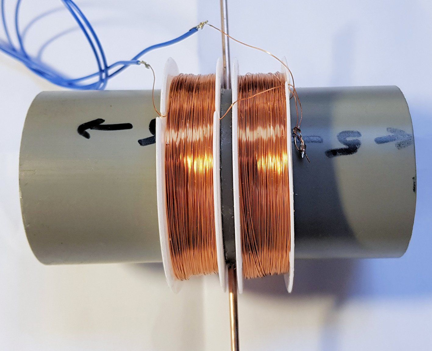
The goal is to create a coil in which the magnets can rotate.
We make the dynamo housing from the PVC pipe.
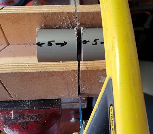
- Cut the PVC pipe neatly into two 5 cm pieces using the hacksaw. Use the miter box for this.
- File a slot exactly down the middle of one of the two pieces that the wire will fit into easily.
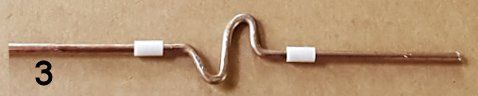
- The most difficult part is making the dynamo's axle. You need to bend an S-shape in the middle of the piece of wire, onto which the magnets will be glued later. Make sure the axle parts are still neatly aligned and that the axle isn't bent.
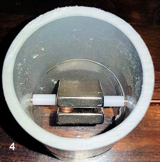
- Separate the magnets and set one aside for a moment. Apply contact adhesive to one side of the other magnet and place the axle on top, right in the middle. Apply some more contact adhesive and place the second magnet directly on top, making sure they attract each other. You can now move them around a bit to ensure the magnets are aligned and perfectly centered on the axle. Let the adhesive dry. Once the adhesive is dry, slide a nylon sleeve onto each end of the axle. Then, place the axle into the slot in the PVC pipe. Glue the other piece of PVC pipe on top, making sure it fits snugly.
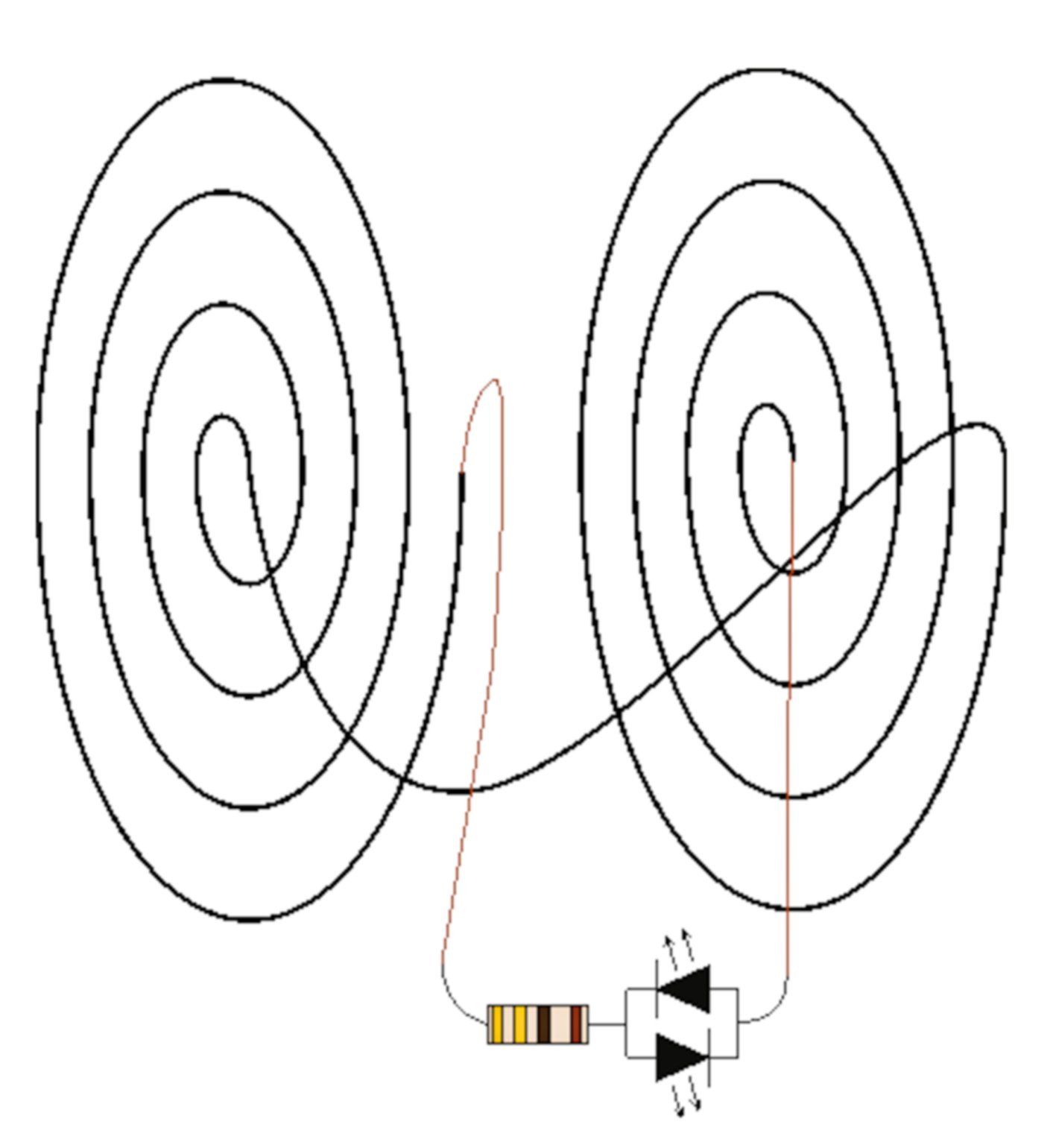
- The coils of winding wire are ready-made coils for your dynamo! Cut the inner plastic disc from the coils and slide them onto the pipe. Make sure both are wound in the same direction. With the coils provided, you can easily do this by keeping the slot where the wire ends fit to the right. Now solder the top wire of one coil to the bottom wire of the other. The remaining wires are the connection wires for your dynamo.
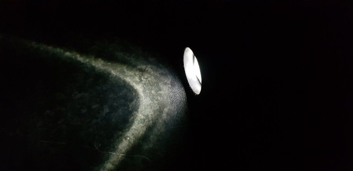
- LEDs have a long leg for the anode and a short one for the cathode. Solder the anode of one LED to the cathode of the other, and vice versa. You now have two LEDs wired in reverse parallel. Now solder one of the leads of the pair to the resistor and the other to one of the dynamo terminals. Solder the loose end of the resistor to the other dynamo terminal. AND GO!


The LED turns on when it gets dark, or when it gets light.
For this circuit you will need:
- 1 x transistor NPN BC547C
- 1 x LED of your choice
- 1 x photosensitive resistor e.g. NSL19M51
- 1 x resistor 150 ohm
- 1 x resistor 220 Kohm
Look in "A to Z" for:
- transistor 120
- Common emitter circuit 121
- Led 100
- Resistance 121
- voltage divider 122
The schedule
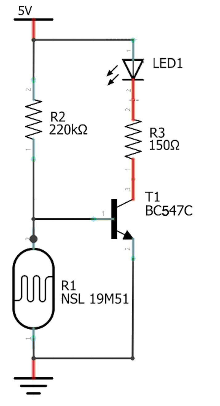
You'll immediately recognize the common emitter circuit. Transistor T1 receives its base current via R2. However, the base is also connected to neutral via photoresistor R3. In series with the collector of T1 are another LED (LED1) and a current-limiting resistor R2.
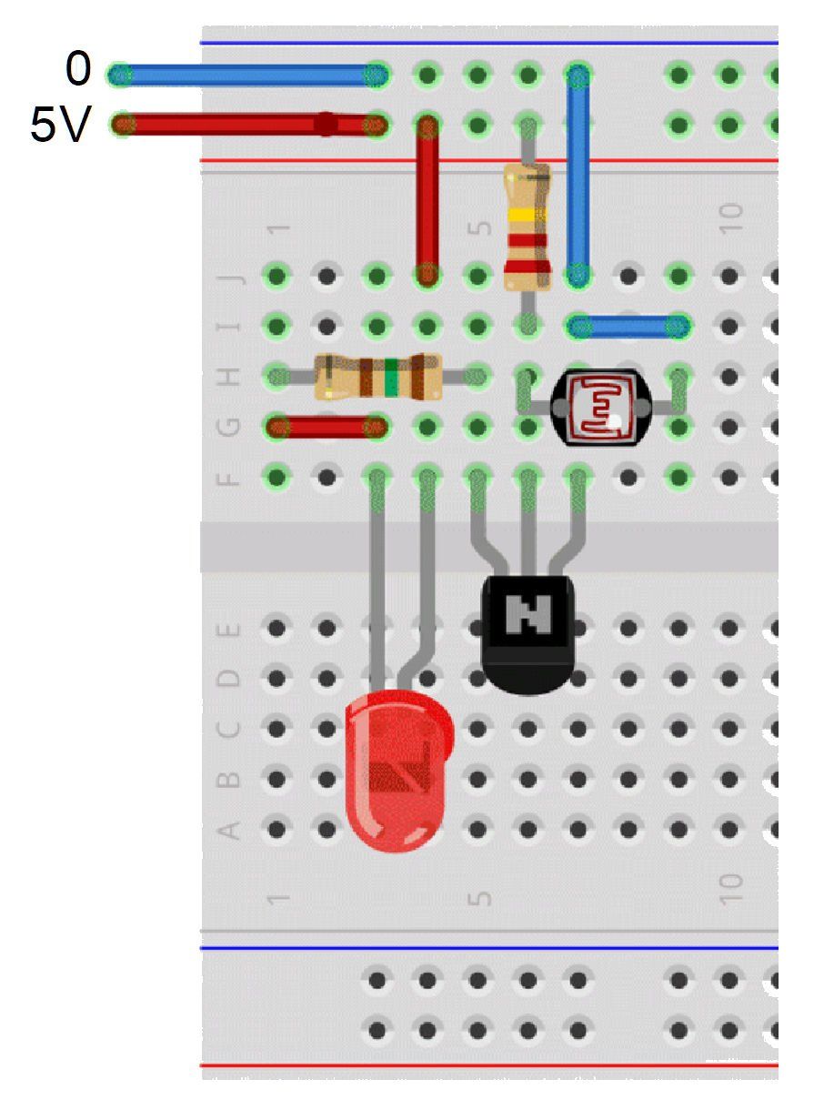
The parts on an experiment board.
You'll probably recognize the LED, the transistor, and the resistors. The photosensitive resistor is located above the transistor on the right. You can test the circuit by placing your finger on this resistor.
This is how it works:
The photosensitive resistor R3, together with the base resistor R1, forms a voltage divider. When the photosensitive resistor is illuminated, its value is so low that the voltage at the base is less than 0.7V. Transistor T1 remains closed. As it gets dark, the resistance of R3 slowly increases. At around 31 kOhms, the transistor begins to open and soon after, it is fully open. The LED is then on. Again, instead of the LED, you can switch other things, such as a buzzer or a small relay to control other things. If you swap R1 and R3, the transistor opens when it gets light. This way, you can make an electronic rooster!

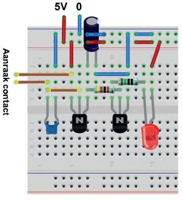
As soon as you touch the two contact points, the LED turns on.
When you release the contact points, the LED will go out again.
For this circuit you will need:
- 2 x BC547C
- 1 x C 100 nF
- 1 x 42 kohm
- 1 x 150 ohm
- 1 x LED of your choice
- Your own skin!
Look in "A to Z" for:
- Capacitor 95
- Common emitter circuit 121
- Led 100
- Transistor 119
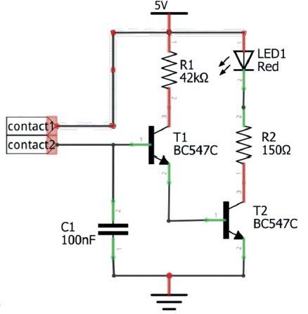
The schedule
Transistor T1's collector is connected to 5 V via resistor R1. T1's emitter is connected to T2's base. T1 thus supplies the base current for T2. T2's collector is connected to 5 V via the LED and R2. T2's emitter is connected to 0. If T2 receives sufficient base current, it will open, and the LED will turn on. T1 has no base resistor. Instead, it has two copper contact points (pieces of copper wire) close together.
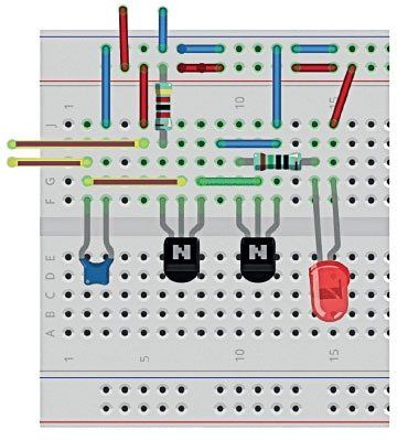
The parts on an experiment board.
In the bottom row, from left to right, you see C1, T1, T2, and the LED. You'll probably recognize the resistors by now. All necessary connections are again made with small pieces of copper wire. The colors are for clarity only.
This is how it works:
Your skin conducts a little, especially when you sweat heavily. It's mainly the moisture (and salt) on your skin that conducts the current. Therefore, the resistance of your skin is not only very high but also quite variable. But we can take advantage of it. T1 receives a small base current through your finger and opens slightly. A collector current flows via R1 to the base of T2. This current is about 200 times greater than T1's base current. So, T2 receives a fairly large base current and will open considerably. A substantial collector current will flow, and the LED will fully activate with a skin resistance of less than 8 MOhms.
You've built an amplifier that amplifies the very small base current of T1, 1 microampere, in two steps to approximately 15mA of collector current of T2. C1 shorts out interfering AC voltages at the input to prevent the LED from spontaneously lighting. The LED's illumination time depends on the type of LED. Choose an LED that lights up well at 10mA and whose forward loss voltage doesn't exceed 2V. Instead of the LED, you can also use a relay to switch completely different functions.
You can only switch off the relay by briefly disconnecting the power supply by pressing S1.
You can see that each part in the diagram is neatly numbered, so you always know which part you are talking about.

When you touch the contact points the LED turns on, when you release the contact points the LED stays on for a while.
For this circuit you will need:
- 2 x BC547C
- 1 x C 100 nF
- 1 x EC 47 µF (emmer condensator)
- 4. 1 x 42 kohm
- 1 x 150 ohm
- 1 x LED of your choice
Look in "A to Z" for:
- Capacitor 95
- Bucket capacitor 96
- Common emitter circuit 121
- Led 100
- Resistance 121
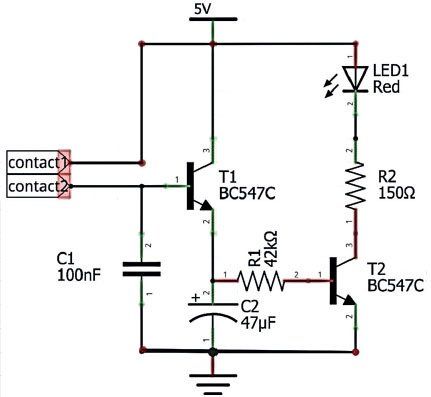
The schedule
You can see that little has changed compared to circuit 3. One component has been added: C2. This is a (bucket) capacitor with a substantial capacity. Furthermore, R1 has been swapped. This resistor is now located between the emitter of T1 and the base of T2. The collector of T1 is now connected directly to 5 V.
The parts on an experiment board.
You'll probably recognize most of the components by now. Note that R1 has been swapped. You'll also see the bucket capacitor or electrolytic capacitor in the top center.
This is how it works:
As soon as you touch the contacts, T1 opens slightly. This is enough to completely fill the bucket C2. The voltage across C2 reaches almost 5V. As soon as you release the contacts, C2 begins to discharge (drain) via R1 to the base of T2. The supply of electrons in C2 is enough to keep T2 open for about 3.5 seconds. The LED will then slowly dim. You can increase the time by increasing the current of C2, but if you choose more than 100 UF, T1 cannot supply enough current to fill it completely. This is the limit of this handy circuit (about 8 seconds).
Later we'll make a circuit that can stick from 30 seconds to 2 hours!

As soon as someone steps on the hidden switch, the LED turns on.
For this circuit you will need:
1. 1 x LED of your choice 2. A 470 ohm resistor at 9 V or 330 ohm at 5 V 3. 1 x switch (make it yourself) 4. A good amount of wire with a braided copper core
Look in "A to Z" for:
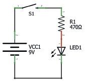
The schedule
In the schematic above, you see a battery on the left. In this case, it's 9V, but the circuit will also work fine on your 5V power supply. (In that case, you'll need to choose 330 ohms for R1.) At the top, you see the pushbutton switch, which is, of course, open. On the right, a resistor and an LED complete the circuit.
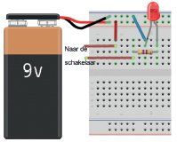
The parts on an experiment board.
Above, on the left, you see the 9V battery. The red "light" is the LED. Below that, you see the 470 ohm resistor. The colored lines are the wires that make the connections. The colors on the resistors indicate their value; the wire colors are just for clarity. They could also all have been black.
This is how it works:
When the tin plates touch, the switch closes, allowing the battery to send current through the circuit. The LED lights up. The resistor ensures the LED receives just the right amount of current to prevent it from breaking. When the switch opens again, the LED also turns off. The switch you've created only makes contact when you press it.
That's called a momentary switch.
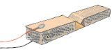
In this case, you can easily make the switch yourself from two strips of tin or copper. Tin and copper are good conductors, and you can easily solder a copper wire to them. Glue two pieces of foam rubber between the tin plates. Make a bend in the center of one of the plates.
Look at the example next to this text. As soon as someone presses the switch, the pictures touch each other and there is contact.
When someone steps on the hidden switch, the LED turns on and stays on until you turn it off yourself.
For this circuit you will need:
- 1 x LED of your choice
- a resistor of 470 ohms at 9 V or 330 ohms at 5 V
- 1 x switch N(normal) O(pen)
- 1 x switch N(normal) G(closed)
- 1 x relay with a coil voltage of 9V (or 5V if you use a 5V power supply) and 2 'normally open' contacts.
- a lot of wire with a braided copper core.
Look in "A to Z" for:
- Battery 95
- Led 100
- Momentary switch 114
- Relay 117
- Switch 113
- Resistance 121
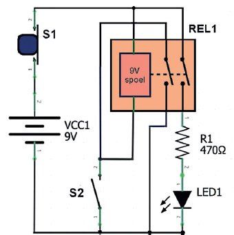
The schedule
On the left, you see the 9V battery. Above it, switch S1 is always closed and only opens when pressed. Next to it is relay REL1 with two switch contacts and a 9V coil (electromagnet). Finally, the switch, the series resistor, and the LED, as in the previous circuit. The lines are the connections. At a junction marked with a dot, the lines make contact.
The circuit consists of two circuits. Circuit 1 runs from the positive terminal of the battery, through the normally closed pushbutton switch S1, and through the coil of relay R1 back to the negative terminal of the battery. This circuit is interrupted by the normally open pushbutton switch S2. The second circuit runs from the positive terminal of the battery, via S1, through the LED and the series resistor, back to the negative terminal of the battery. This circuit is interrupted by the second switching contact of the relay.
The first switching contact of relay R1 is parallel to pushbutton switch S2
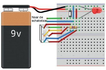
The parts on an experiment board.
On the left, you see the 9V battery. The red "light" is the LED. To the left of that is switch S1, which interrupts the power supply. Below the LED, you can see the 470 ohm resistor. The relay is upside down next to the experiment board. The wires are soldered to the legs. The colored lines are the wires that make the connections. The colors are for clarity only.
This is how it works:
When someone presses S2, the relay coil receives power from the battery. The relay energizes, and the contacts close. The LED now receives power through contact 1 of the relay and resistor R1, and thus turns on. The second relay contact short-circuits pushbutton S2, keeping the relay energized even when the pushbutton loses contact. This is called a latching circuit.
You can only turn off the relay by briefly disconnecting the power supply by pressing S1. You'll notice that each component in the schematic is clearly numbered, so you always know which one you're talking about.